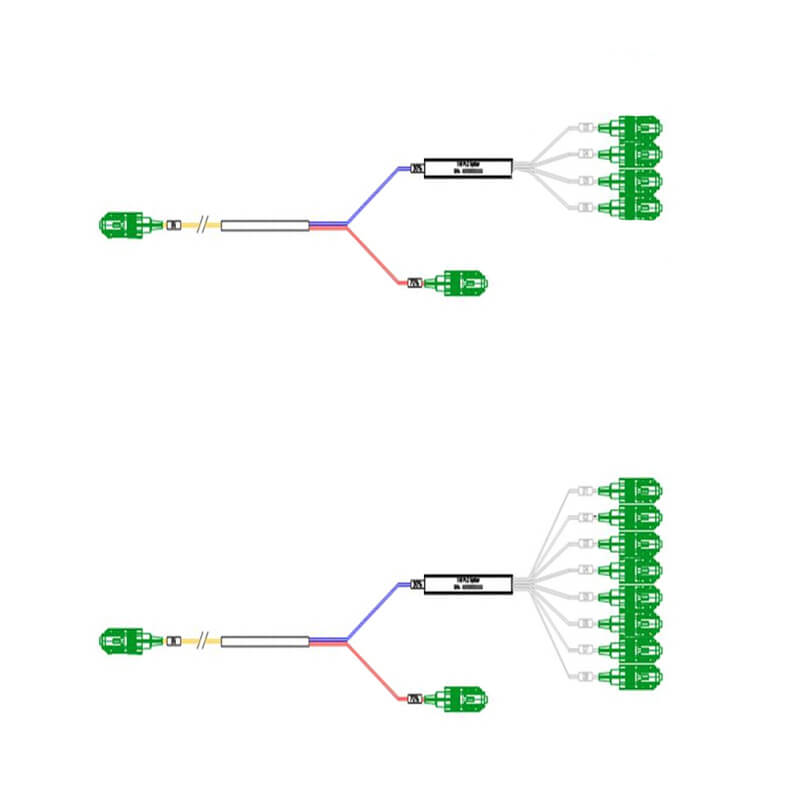
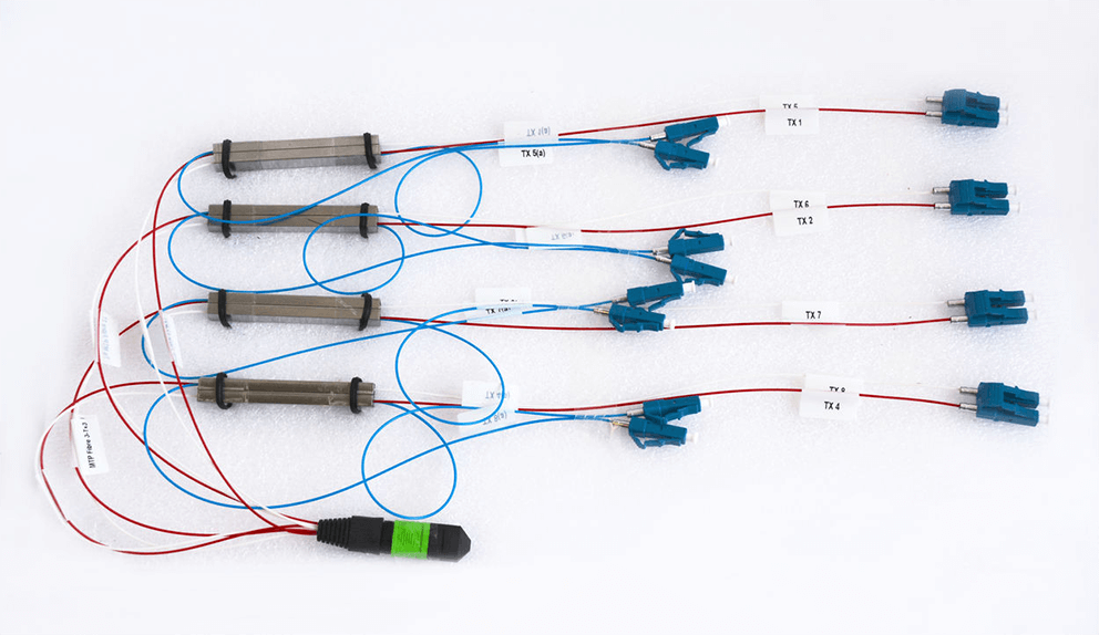
Optical fiber splitter is a device used to realize the splitting and combining of light beams. It distributes the light beam transmitted in one optical fiber to two or more optical fibers according to a predetermined ratio, or combines the optical transmitted in multiple optical fibers into one optical fiber.
When choosing an optical splitter, in addition to considering usage scenarios and needs, you can also refer to performance parameters. The parameters that affect the optical splitter performance generally include the following.
Another guide about how to choose optic splitters

Insertion loss
The insertion loss of the fiber optic splitter refers to the dB of each output relative to the input optical loss, and its mathematical expression is: Ai=-10lg Pouti/Pin, where Ai refers to the insertion loss of the ith output port; Pouti is the optical power of the ith output port; Pin is the optical power value of the input port. Generally speaking, the smaller the insertion loss, the better.
Additional loss( Excess loss)
The additional loss refers to the DB number of the total optical power of all output ports relative to the input optical power loss. For optical fiber splitter, the additional loss is an index reflecting the quality of the device manufacturing process. However, the insertion loss only represents the output power status of each output port, not only the inherent loss factor, but also the influence of the splitting ratio. Therefore, between different splitters, the difference in insertion loss does not reflect the quality of device fabrication.
The additional loss for 1*N single-mode fiber splitter is shown in the following.
| Ways | 2 | 3 | 4 | 5 | 6 | 7 | 8 | 9 | 10 | 11 | 12 | 16 |
| excess loss(dB) | 0.2 | 0.3 | 0.4 | 0.45 | 0.5 | 0.55 | 0.6 | 0.7 | 0.8 | 0.9 | 1.0 | 1.2 |
Splitting ratio
The splitting ratio is defined as the output power ratio of each output port of the fiber splitter. Usually, the splitting ratio of PLC optical splitter is evenly distributed, and the splitting ratio of FBT optical splitter can be unequally divided. The specific ratio setting of the splitting ratio is related to the wavelength of the transmitted light. For example, when an optical branch transmits light of 1.31 μm, the splitting ratio of the two output ends is 50:50; when transmitting light of 1.5 μm, it changes to 70:30. The reason is that the optical fiber splitter has a certain bandwidth, that is, the frequency bandwidth of the transmitted optical signal when the splitting ratio is basically unchanged. In network applications, the splitting ratio is based on the amount of optical power required by the optical node of the actual system to determine the appropriate splitting ratio (except for the equal distribution).

Isolation
It refers to the isolation ability of a certain optical way of a fiber optic splitter to optical signals in other optical ways. The isolation degree is significant for the fiber optic splitter. In practical system applications, optic splitters with an isolation degree of more than 40dB are often required, otherwise, the performance of the entire system will be affected.
Return loss
Return loss, also known as reflection loss, refers to the power loss in an optical signal returned or reflected by a discontinuity in an optical fiber or transmission line. The higher the return loss, the better to reduce the impact of reflected light on the light source and system.
Uniformity
The uniformity of the optical splitter is related to the insertion loss, that is, the maximum insertion loss and the minimum insertion loss value is the uniformity value. The uniformity of FBT is poor, the uniformity value of 1X4 is about 1.5dB, and the uniformity value above 1×8 is larger, which cannot ensure uniform light splitting and may affect the overall transmission distance. PLC splits the light evenly, which can equally distribute signals to users.
Directionality
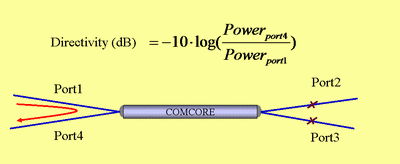
In an optical splitter, directivity describes the degree of influence of light entering from an output end through the device on adjacent output ends.

PDL (Polarization-dependent loss)
PDL is the ratio of the maximum transmission to the minimum transmission of an optical device in all polarization states. In other words, the amount of change in insertion loss IL during vibration. In the field of communication and sensing, PDL is a very important indicator, which reflects the sensitivity of a device to different polarization states.
TDL (Temperature dependent loss)
In some areas, the temperature can be a key factor affecting the insertion loss of an optical element. Once the working temperature of splitter is out of range, insertion loss will increase and influence the performance of splitter. FBT splitters can work stably from -5 to 75°C. PLC splitters can operate in a wider temperature range of -40 to 85°C, providing relatively good performance in extreme climate regions.
Stability
Stability means that when the external temperature changes and the working state of other devices changes, the splitting ratio and other performance indicators of the fiber optic splitter should remain basically unchanged. In fact, the stability of the fiber optic splitter depends entirely on the manufacturer’s craftsmanship.
At the end
Fiber splitters are especially suitable for connecting MDF and terminal equipment to distribute optical signals in passive optical networks (EPON, GPON, BPON, FTTX, FTTH, etc.). Optical fiber splitter is one of the most important passive devices in optical fiber links. When choosing optic splitter, you can refer to the performance parameters. Bonelinks, as an optical splitter manufacturer, provides a variety of high-performance splitters, featuring with high stability, high return loss, low additional loss, etc. Please contact us if you have any needs.


