An optical splitter is a device that divides light transmission in a network into multiple output ends. It plays a crucial role in facilitating network interconnections.
This article aims to provide a comprehensive understanding of the working principle, various types, applications, and selection criteria for optical splitters.
What is Optical Splitter?
Fiber optic splitters have become a vital component in modern optical network topologies, enabling users to optimize the efficiency of optical network circuits.
Also known as optical splitters, fiber splitters, or beam splitters, these devices are waveguide-based optical power distribution units.
They divide an incoming light beam into multiple beams and vice versa, featuring multiple input and output points. Optical splitters play a significant role in passive optical networks (such as EPON, GPON, BPON, FTTX, FTTH, etc.), enabling the sharing of a single PON interface among multiple subscribers.
How does Optical Splitter Work?
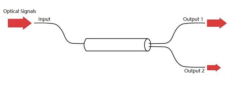
When an optical signal travels through a single-mode fiber, the complete concentration of light energy within the core for transmission is not achieved. Instead, a small portion of light energy propagates near the cladding of the fiber.
In general, when the cores of two fibers are positioned closely, the optical signal sent through one fiber can enter the other fiber. This phenomenon enables the redistribution of the optical signal between the two fibers, forming the basis of a fiber splitter.
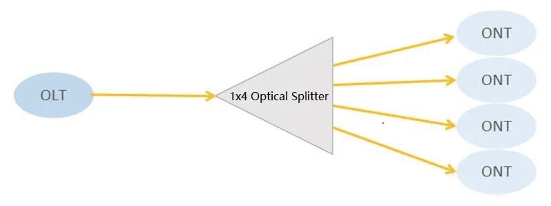
For instance, a 1×4 fiber optic splitter evenly divides an optical signal from one fiber into four separate fibers. To illustrate, a 1000Mbps bandwidth is equally distributed among four households, allowing each household to access the network with a bandwidth of 250Mbps.
What are the Benefits of Using Optical Splitters?
The utilization of splitters offers two significant benefits:
- Scalability Enhancement: Optical splitters contribute to the scalability of networks. Optical splitter permits gradual network expansion over time, eliminating the need for additional ports or extensive fiber cabling.
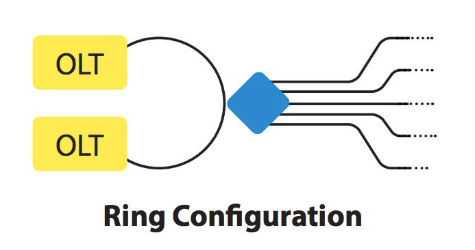
- Redundancy Improvement: Apart from scalability, optical splitters contribute to network reliability. Particularly, splitters with a 2:N configuration (two inputs) are commonly employed in a ring arrangement to bolster the physical redundancy of the network. This redundancy setup increases network resilience and minimizes the impact of potential failures.
Optical Splitter Types
Classified by Package Style
Optical splitters are categorized based on their package style and connector termination. They can come in different forms, with the primary packaging being either box type or stainless tube type. The box type fiber splitter is commonly employed with cables of 2mm or 3mm outer diameter, while the stainless tube type is typically used with 0.9mm outer diameter cables. These splitters are available in various split configurations, including 1×2, 1×8, 2×32, 2×64, and more.
Classified by Transmission Medium
Optical splitters can be categorized based on the transmission mediums they are optimized for: single mode optical splitters and multimode optical splitters. Multimode optical splitters are designed for operation at 850nm and 1310nm wavelengths, while single mode optical splitters are optimized for 1310nm and 1550nm wavelengths.
Additionally, optical splitters can also be classified based on their working wavelengths: single window and dual window optical splitters. Single window optical splitters operate using a single working wavelength, while dual window optical splitters use two different working wavelengths.
Classified by Manufacturing Technique
The FBT (Fused Biconic Taper) splitter employs conventional technology by fusing multiple fibers together from their sides, resulting in lower costs. On the other hand, the PLC (Planar Lightwave Circuit) splitter utilizes planar lightwave circuit technology and is available in various split ratios such as 1:4, 1:8, 1:16, 1:32, and 1:64. It comes in different types like bare PLC splitter, steel tube PLC splitter, ABS splitter, LGX box splitter, fanout PLC splitter, and mini plug-in type PLC splitter.
How to Apply Fiber Optic Splitters In PON System?
Fiber optic splitters find widespread application in Passive Optical Network (PON) systems, where they play a crucial role in distributing optical signals among multiple fibers with different configurations (1×N or M×N). PON networks, particularly in scenarios like Fiber to the Home (FTTH), heavily utilize these splitters. The typical FTTH architecture consists of an Optical Line Terminal (OLT) in the central office, an Optical Network Unit (ONU) at the user’s end, and an Optical Distribution Network (ODN) connecting the two. An optical splitter is commonly employed in the ODN to enable multiple end-users to share a single PON interface.
For point-to-multipoint FTTH network deployments, the distribution section can be categorized into centralized (single-stage) or cascaded (multi-stage) splitter configurations. In a centralized splitter setup, a single-stage splitter is placed at the central office in a star topology. In contrast, the cascaded splitter approach utilizes multi-layer fiber splitters in a point-to-multipoint topology.
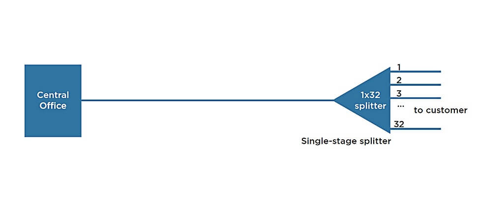
Fiber Optic Splitter In Centralized PON Architecture
In a centralized Passive Optical Network (PON) architecture, a common approach is to employ 1×32 splitters within the central office, which can be positioned at any location within the network. In this setup, the input port of the splitter is directly linked to a GPON/GEPON Optical Line Terminal (OLT) through a single fiber.
On the opposite side of the splitter, 32 individual fibers are routed through distribution panels, splice ports, and/or access point connectors, extending to the homes of 32 customers. At these customers’ residences, the fibers are connected to Optical Network Terminals (ONTs). In essence, this PON network configuration facilitates the connection of one OLT port to 32 ONTs, allowing for efficient signal distribution to multiple end-users.
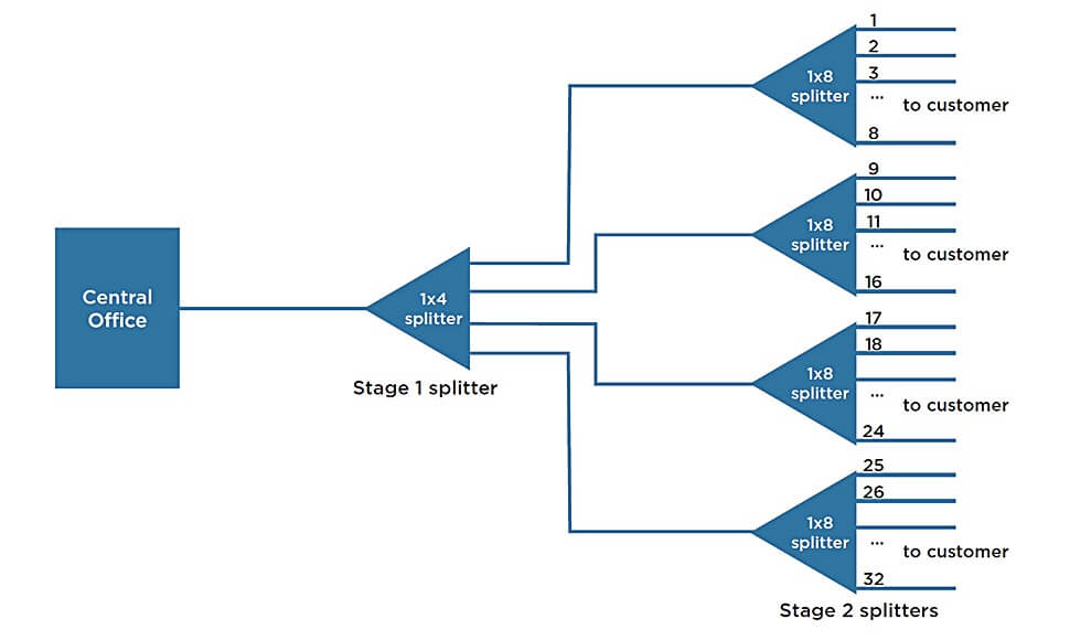
Fiber Optic Splitter In Cascaded PON Architecture
In a cascaded PON architecture, a 1×4/1×8 fiber splitter can be positioned within an outdoor plant enclosure or terminal box. This splitter is directly linked to an OLT port in the central office. Each of the four fibers emanating from this initial stage 1 splitter is directed to an access terminal housing a 1×8/1×4 splitter for stage 2.
As a result, a total of 32 fibers (4×8) would extend to reach 32 individual residences. It’s feasible to implement more than two splitting stages within a cascaded setup, and the overall split ratio may vary accordingly (e.g., 1×16 = 4 x 4, 1×32 = 4 x 8, 1×64 = 4 x 16, 1×64 = 8 x 8). This configuration allows for efficient distribution of signals to multiple users through a series of splitters and access terminals.
How to Choose the Right Fiber Splitter?
When selecting the right fiber optic splitter, it’s important to consider various performance indicators that can impact its effectiveness. Here are some key factors to keep in mind:
- Insertion Loss: This measures the optical power loss when the signal passes through the splitter. Lower insertion loss values indicate better splitter performance.
- Return Loss: Also known as reflection loss, this refers to the loss of optical power due to signal reflections within the splitter. A higher return loss is preferable.
- Splitting Ratio: The ratio of output power from the splitter’s output ports in the system application, which is influenced by the transmitted light’s wavelength.
- Isolation: This indicates the extent to which the splitter isolates optical signals in one path from those in other paths.
- Uniformity: Uniformity measures the evenness of power distribution among the output ports.
- Directivity: This indicates how well the splitter separates signals from different input ports.
- PDL (Polarization Dependent Loss): PDL measures how the splitter’s performance varies with different polarization states of light.
In terms of specific choices, there are two main types of splitters: Fused Biconic Taper (FBT) and Planar Lightwave Circuit (PLC) splitters.
- FBT Splitter: FBT splitters are cost-effective and suitable for certain applications. They offer a lower initial cost and are suitable for configurations below 1×4. They work well for single or dual wavelength transmission scenarios.
- PLC Splitter: PLC splitters are known for their flexibility, stability, low failure rates, and broader temperature ranges. They are recommended for high-density applications and configurations above 1×8. PLC splitters are better suited for PON broadband transmission due to their potential for future expansion and monitoring needs.
Cost considerations play a role as well. PLC splitters are generally more expensive due to their complex manufacturing technology. When choosing between FBT and PLC splitters, evaluate your specific requirements, including split configurations, wavelength transmission, and potential future expansion needs.
In summary, carefully assess your performance requirements, anticipated expansion, and budget constraints when choosing between FBT and PLC splitters to ensure the most suitable solution for your optical network needs.
Future of Fiber Optic Splitters
Fiber optics have transformed telecommunications, with PLC splitters crucial for FTTH connections. Asymmetric PLC splitters, though less common, offer advantages like flexible network setup, cost savings, quick deployment, and enhanced monitoring. They find use in distributed splits and daisy-chain architectures, benefiting FTTH deployments. While specialized splicing is needed, the benefits outweigh the drawbacks.
Conclusion
Optical splitters play a vital role in distributing signals across multiple optical fibers. These passive devices are essential components in fiber-optic networks, requiring no electronics or power. Selecting the right fiber optic splitters is crucial for optimizing optical infrastructure and building a durable network architecture for the long term.