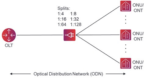
The traditional ODN (Optical Distribution Network) typically employs a uniform fiber splitting approach, with fiber splitters mainly in configurations of 1×4, 1×8, or 1×16, as illustrated in Figure 1.
However, in the ODN with uniform fiber splitting, a larger number of fiber cores are introduced into the optical cable, leading to higher project costs.
Therefore, in certain specific scenarios, such as FTTR (Fiber to the Room), a non-uniform fiber splitting approach is gradually being adopted in the ODN.
1. What is Non-uniform Fiber Splitting?
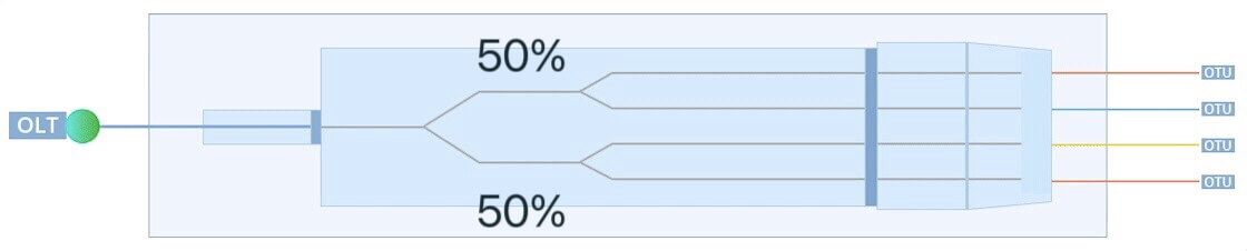
In uniform power splitting, the optical power at each output port of the splitter is consistent, meaning that the insertion loss at each output port is the same.
For example, in a 1×4 optical splitter, the optical power at each output port is approximately 25% of the input port’s optical power, as illustrated in Figure 2.
Non-uniform power splitters have inconsistent optical power at their output ports.
Taking a 1×2 non-uniform optical splitter as an example, common optical power distribution ratios at the two output ports include 10/90, 15/85, 20/80, 30/70, etc., as shown in Figure 3.
Commonly used non-uniform optical splitter models in ODN are designated as 1×N, indicating one input port, one cascading port, and (N–1) output ports.
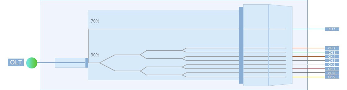
Frequently used models in projects are 1×5 and 1×9. Non-uniform fiber splitters are typically created by cascading a uniform splitter onto the output port with lower optical power in a 1×2 non-uniform optical splitter.
For instance, a 1×5 fiber splitter involves cascading a 1×4 splitter onto the output port of a 15/85 splitter, as illustrated in Figure 4, and a 1×9 fiber splitter involves cascading a 1×8 splitter onto the output port of a 30/70 splitter.
In these cases, the direct output port of the 1×2 non-uniform optical splitter serves as the cascading port, and the output ports of the uniform splitter serve as service ports.

2. Insertion Loss of Non-uniform Power Splitters
The insertion loss at the cascading port of non-uniform power splitters is relatively small, making them highly suitable for cascading multiple splitters to form a chained ODN network, as illustrated in Figure 5.
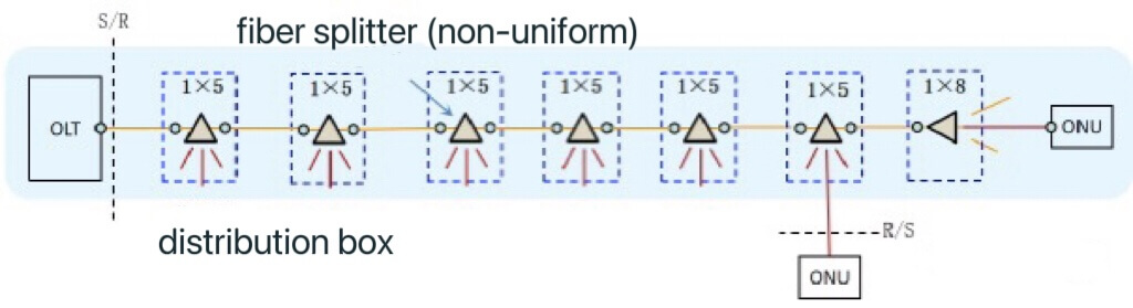
In a chained network configuration, the maximum number of users that a single PON port can accommodate is directly proportional to the number of cascaded splitter stages.
The number of splitters that can be cascaded in an ODN link is mainly influenced by the insertion loss of the splitters. The insertion losses for commonly used 1×5 and 1×9 splitters are listed in Table 1.
Table 1: Insertion Loss of Non-uniform Optical Splitters
| Item | Splitting Ratio | Port | Insertion loss (dB) | |
| Manufacturer A | Manufacturer B | |||
| 1×5 fiber splitter | 85% | Cascade Port | 1.45 | 1.75 |
| 15% | Output Port | 15.35 | 15.4 | |
| 1×9 fiber splitter | 70% | Cascade Port | 1.9 | 1.8 |
| 30% | Output Port | 15.7 | 15.8 | |
3. Non-uniform Power Splitting ODN Link Models
The ODN link models with non-uniform power splitting primarily adopt single-chain and double-chain network structures, while it is not advisable to use a multi-branch network structure.
3.1 Single-Chain Non-uniform Power Splitting
When the ODN employs a single-chain structure (refer to Figure 5), the transmission distance of the PON is as shown in Table 2.
Table 2: Transmission Distance of PON in Single-Chain Configuration
| Item | Unit | 1×5 | 1×9 |
| Maximum Allowable Channel Insertion Loss | dB | 29 | 29 |
| Optical Splitter Cascade Insertion Loss | dB | 1.8 | 2 |
| Optical Splitter Input Insertion Loss | dB | 15.7 | 17 |
| Other Active Connection Insertion Loss (see remark) | dB | 1.5 | 1.5 |
| Line Maintenance Margin | dB | 1 | 1 |
| Fiber and Splicing Attenuation per Kilometer | dB/km | 0.26 | 0.26 |
| Number of Distribution Boxes | pcs | 7 | 6 |
| Transmission Limited Distance | km | 6.9 | 5.8 |
| Maximum Installed User Count | pcs | 32 | 48 |
| Note: Refers to the active connection insertion loss at the ODF (Optical Distribution Frame) and optical cable junction box. | |||
From Table 2, it can be observed that when using the single-chain network structure depicted in Figure 5, the total number of distribution boxes on the chain should not exceed 6 (when using a 1×9 splitter) and 7 (when using a 1×5 splitter).
3.2 Double-Chain Non-uniform Power Splitting
When the number of distribution boxes in a single “chain” is relatively low, a PON port can also be split into two branches using a 1×2 uniform power splitter, as shown in Figure 6.
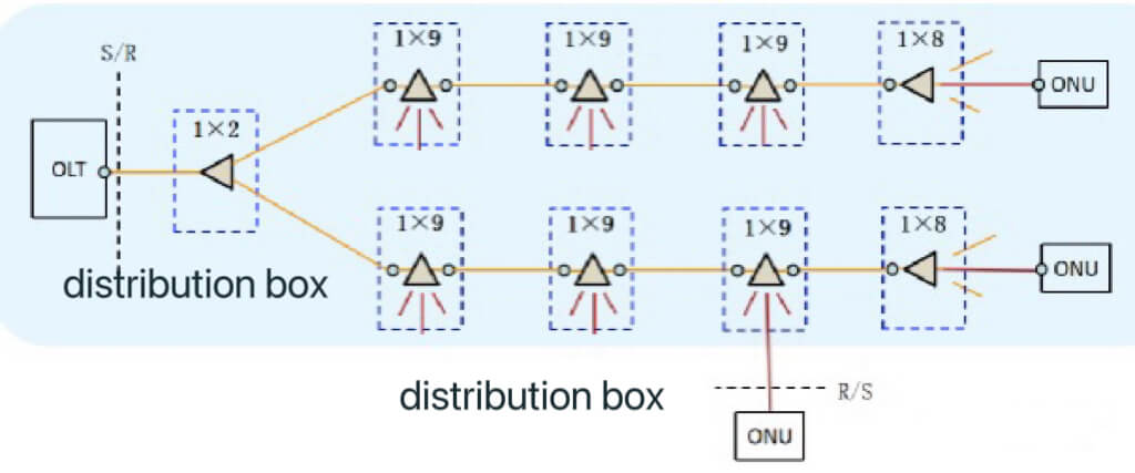
For the network structure depicted in Figure 6, the transmission distance of the PON and the maximum number of users a PON port can accommodate are listed in Table 3.
Table 3: Transmission Distance of PON in Double-Chain Configuration
| Item | Unit | 1×5 | 1×9 | ||
| 1×2 Uniform Power Splitter Insertion Loss | dB | 4.4 | 4.4 | 4.4 | 4.4 |
| Number of Distribution Boxes on a Single Chain | pcs | 4 | 5 | 3 | 4 |
| Transmission Limited Distance | km | 10.8 | 3.8 | 11.9 | 4.2 |
| Maximum Installed User Count | pcs | 40 | 48 | 48 | 64 |
3.3 Multi-Branch Non-uniform Power Splitting
Although the non-uniform power splitting ODN link also supports up to 4 branches, as shown in Figure 7, this configuration does not significantly differ from the chain models of uniform power splitting. It also fails to fully leverage the advantages of non-uniform power splitting.
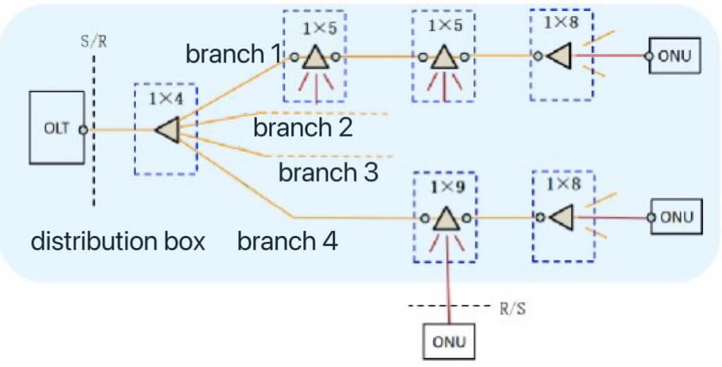
For an ODN with 4 branches, the transmission distance and the maximum number of users a PON port can accommodate are detailed in Table 4.
Table 4: Transmission Distance of PON in Multi-Branch Configuration
| Item | Unit | 1×5 | 1×9 | |
| 1×4 Uniform Power Splitter Insertion Loss | dB | 8 | 8 | 8 |
| Number of Distribution Boxes on a Single Chain | pcs | 2 | 3 | 2 |
| Transmission Limited Distance | km | 10.8 | 3.8 | 5.8 |
| Maximum Installed User Count | pcs | 48 | 64 | 64 |
4. In Conclusion
As the transmission distances of PON in Tables 2 to 4 are calculated based on worst-case scenarios, when constructing ODN according to the aforementioned link models, there is often a redundancy of 2.0dB to 4.0dB in ODN link attenuation.
Therefore, the actual number of distribution boxes on each branch of the ODN link tends to be one more than that shown in Figures 5 to 7.
Non-uniform power splitting is suitable for a chained network structure.
In comparison to uniform power splitting, the security of non-uniform power splitting links is lower, with fewer users per PON port.
It is more suitable for use in rural areas when employing GPON access. Although non-uniform power splitting also supports multi-chain and other flexible power splitting methods, it increases the difficulty of construction, maintenance, and management, and is not recommended for adoption.