Due to different construction conditions and requirements, optical cables may be laid in different ways in various scenarios. Common installation methods include direct burial, overhead, pipeline, underwater, and indoor installations.
1. Direct Burial Installation
Direct burial, also known as direct burial installation, refers to laying optical cables directly underground in the soil. Typically, in regular or hard soil, optical cables should be buried below 1.2 meters from the surface.
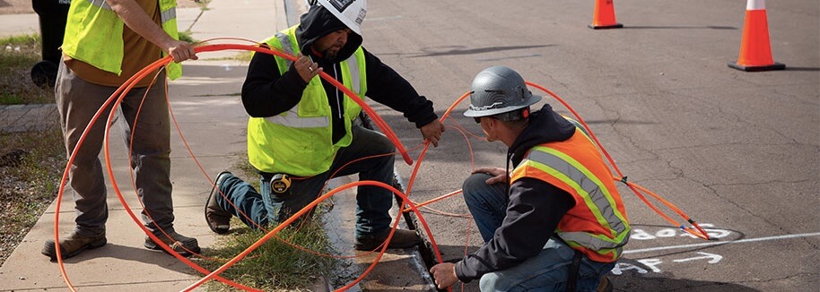
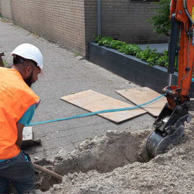
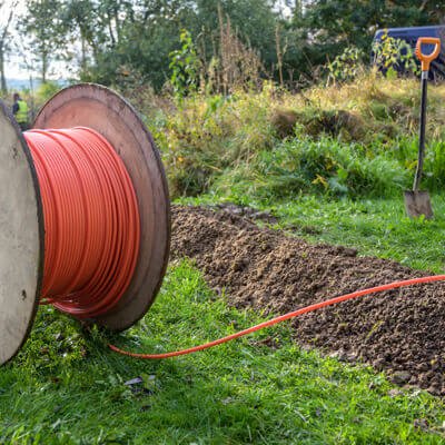
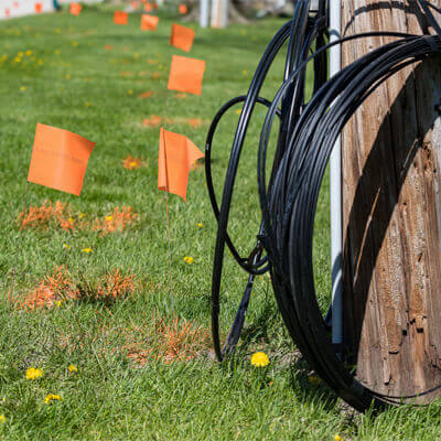
During the construction of direct burial optical cables, a trench that meets the requirements (see Figure 1A) is first excavated. Subsequently, the buried optical cable is laid at the bottom of the trench (see Figure 1B), and then the soil is backfilled. To facilitate locating the cable during maintenance, marker stones are buried on the surface approximately every 50 meters after backfilling (see Figure 1C). Direct burial of optical cables can be done manually or by using mechanical installation methods (see Figure 1D).
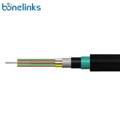
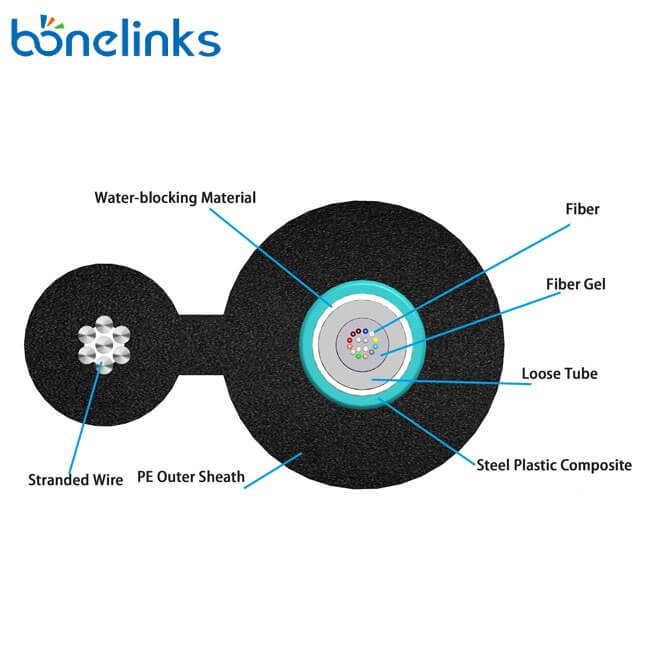
The direct burial optical cable is a communication outdoor fiber optic cable with a metal strengthening member, loose tube stranding, and filled aluminum-polyethylene bonded sheath. An additional chrome-plated steel strip and polyethylene outer sheath, as shown in Figure 2, enhance the cable’s protective performance.
The safety of direct burial optical cable lines is relatively good, but they come with higher construction and maintenance costs and are challenging to expand. Consequently, they are gradually being replaced by methods like long-distance plastic conduit air blowing. Currently, in sparsely populated areas where overhead installation is not suitable (e.g., grasslands, deserts), there is still limited construction of direct burial optical cables.
From a project management perspective, the construction of long-distance plastic conduit buried in the field is similar to direct burial optical cables. Therefore, some project managers often manage projects involving air-blown optical cables through long-distance plastic conduit burial as if they were direct burial optical cable projects. However, in terms of cable installation, it should be classified as conduit optical cable installation.
2. Overhead Installation
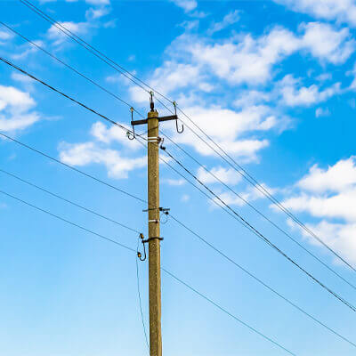
Overhead installation of optical cables refers to suspending the cables from supporting structures such as utility poles, keeping them in a space approximately 3.0 to 8.0 meters above the ground. The primary support structures for overhead optical cables are typically utility poles, with a pole-to-pole distance (spacing between adjacent utility poles) generally around 50 meters.
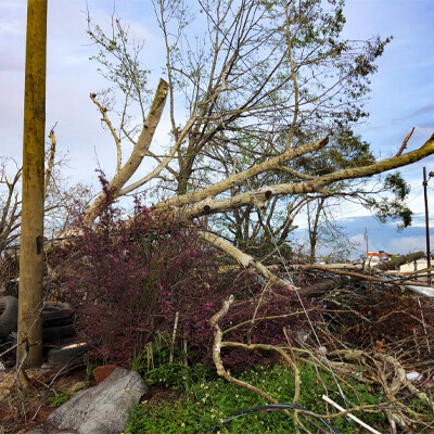
The construction cost of overhead optical cables is relatively low, but the safety level is also lower. These cables are susceptible to being accidentally cut by oversized vehicles when crossing roads. Additionally, during floods, there is a risk of extensive pole roads being washed away.
Overhead Installation Methods: Utilizing Steel Strand Suspension and Self-supporting Aerial
2.1 Utilizing Steel Strand Suspension
The overhead optical cable is primarily installed using the steel strand suspension method. In this approach, steel strand wires are first fixed on utility poles, and then the optical cable is hung on the steel strand using cable hooks, as illustrated in Figure 5. Typically, each utility pole can have 1 to 4 steel strands fixed, and each steel strand can suspend 1 or more optical cables.
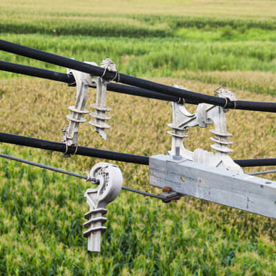
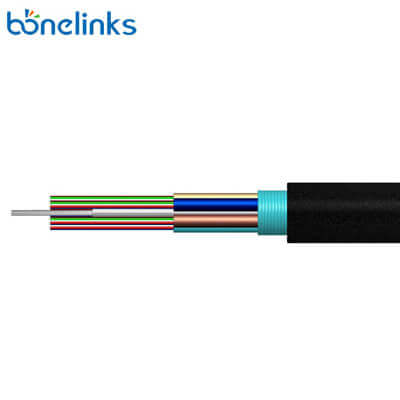
The outer sheath of the overhead optical cable is equipped with a layer of steel tape armor between the protective layer and the cable core (as shown in Figure 6). This design provides the optical cable with some resistance against bird pecking and rodent damage.
2.2 Self-supporting Aerial
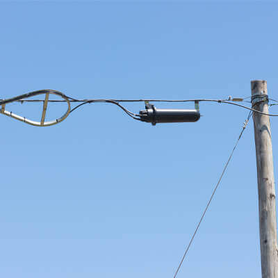
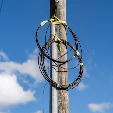
Self-supporting aerial refers to the use of a self-supporting optical cable with high tensile strength, eliminating the need for steel strand suspension (as shown in Figure 7). This type of optical cable is directly fixed to supporting structures such as utility poles. Self-supporting aerial is often employed in scenarios where it is inconvenient to use steel strand suspension, such as under power poles, in areas with strong air corrosion, or in sections where cable expansion is not required for an extended period.
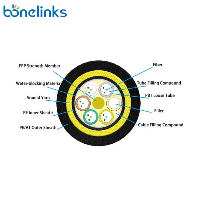
In scenes along high-voltage power lines or where large spans are needed, self-supporting optical cables typically adopt an ADSS (All-Dielectric Self-Supporting) structure. The primary load-bearing component of the cable is aramid yarn between the inner protective layer and the outer sheath, as depicted in Figure 8.
For scenarios requiring cost-effective construction, self-supporting optical cables often use an “8-shaped” structure, with the main load-bearing component being the messenger wires within the cable, as shown in Figure 9.
3. Pipeline Installation
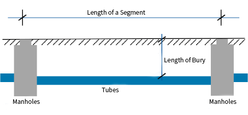
Pipeline installation of optical cables typically involves laying the cables inside underground communication pipelines through methods like pulling or air blowing. Underground communication pipelines usually consist of buried pipe clusters and manholes at both ends, as shown in Figure 10. Pipe clusters are typically made up of one or more plastic pipes. Depending on the construction area and segment length, underground communication pipelines are usually categorized into local pipelines and long-distance pipelines.
3.1 Local Pipelines
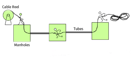
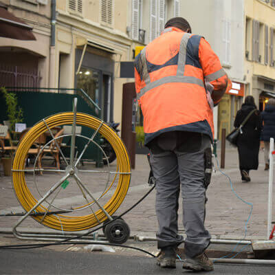
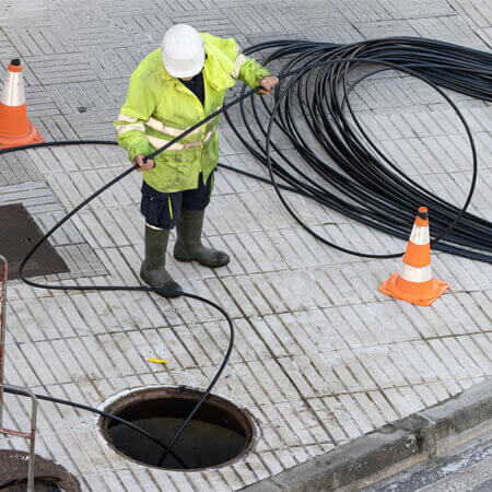
Local pipelines are typically constructed in urban areas, suburbs, or towns where communication services are more densely populated. The segments are approximately 100 meters long. Optical cables are usually laid in the pipeline through manual pulling (see Figure 11A) or mechanical pulling (see Figure 11B) methods.
3.2 Long-Distance Pipelines
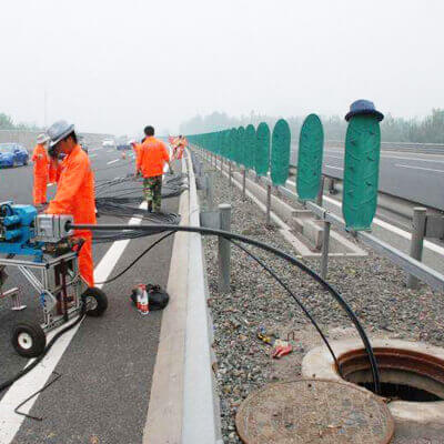
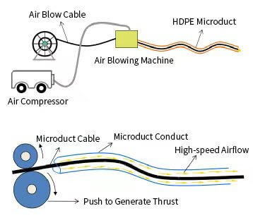
Long-distance pipelines are typically constructed in remote outdoor areas, using 40mm/33mm silicon core plastic pipes, with segments approximately 980 meters long. Optical cables are laid in the pipeline through air blowing, as shown in Figure 12A. Air blowing installation involves injecting compressed air into the silicon core pipe, causing the optical cable to be suspended in a high-speed airflow within the silicon core pipe. Simultaneously, the cable blowing machine’s caterpillar conveyor mechanism grips the cable and moves it forward, as illustrated in Figure 12B.
4. Micro Duct and Micro Cable Installation Methods
To enhance the utilization of duct resources, micro duct and micro cable installation methods have become widespread along the communication pipelines alongside highways.
Micro ducts are classified into standard and reinforced types based on different deployment methods. Standard micro ducts have thinner walls and are primarily used for air blowing within existing silicon core pipes. They can also be manually installed in empty ducts without existing optical cables.
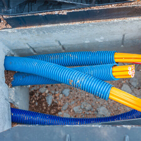
Reinforced micro ducts have thicker walls and are suitable for scenarios requiring high tensile or compressive strength. This includes situations such as laying them within existing ducts with optical cables or providing protection for micro cables within handholes.
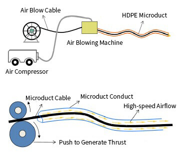
Air-blown micro cables use a mechanical pusher to propel the micro cable into the micro duct. Simultaneously, a compressed air compressor delivers a powerful airflow into the micro duct. The high-speed flowing air inside the micro duct creates a forward thrust on the surface of the optical cable, propelling it forward. The maximum segment length for a single air-blowing operation can exceed 1000 meters. The same principle applies to air blowing micro ducts within silicon core pipes.
5. Optical Cable Installation in High-Speed Rail Tunnels
Installing optical cables along high-speed rail routes not only reduces construction difficulty and enhances safety but also shortens relay distances and reduces transmission delays for communication trunk lines. In recent years, the construction of trunk optical cables along high-speed rail routes has become increasingly common. The high-speed rail infrastructure itself requires both power and communication services, with strong and weak current ducts positioned on both sides of the tracks. Communication optical cables are laid within the weak current ducts, as illustrated in Figure 15.
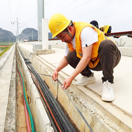
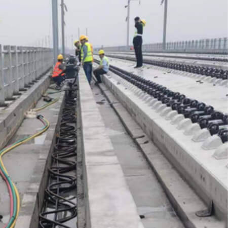
Due to the limited cross-sectional dimensions of the weak current duct, optical cables are typically installed with a serpentine pattern to accommodate excess length, as shown in Figure 16. Cable joints are left on both sides of the optical cable, with a spacing of approximately 500 meters between them.
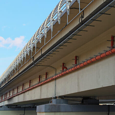
High-speed rail construction typically involves elevated structures. When bringing communication optical cables out of the railway, they are laid using a bridge rack on the bridge piers, as depicted in Figure 17.
The outer layer of the optical cable laid through the weak current duct of the high-speed rail is made of low-smoke, halogen-free, flame-retardant polyolefin. Therefore, the optical cable possesses a certain flame-retardant performance.
6. Submarine Optical Cable Installation
When direct burial optical cables pass through water channels, rivers, or ponds, they usually need to be laid underwater. In this context, “underwater” refers to water bodies excluding large lakes, oceans, major rivers, and other extensive underwater distances. The installation methods for underwater optical cables mainly include diversion trenching, water pumping trenching, and directional drilling.
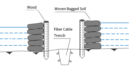
6.1 Diversion Trenching
Diversion trenching involves first blocking the water in the channel or river with a water barrier. After draining the water from the section where the optical cable trench needs to be excavated, the subsequent steps, such as digging the optical cable trench, are carried out, as shown in Figure 18. The water barrier can be temporary and constructed using filled woven bags or reinforced with logs when the water is deep. When dealing with flowing water in channels or rivers, it is typically sufficient to divert the flow upstream of the optical cable trench. The unit length cost of diversion trenching for cable installation is usually relatively high.
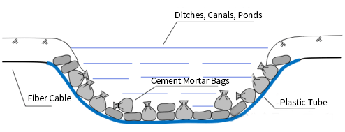
6.2 Water Pump Trenching
Water pump trenching typically requires divers equipped with underwater tools to perform the construction underwater. Divers first use a high-pressure water gun to create a trench on the water bottom, approximately 1.5 meters deep. They then place plastic pipes in the trench and use cement mortar bags to press the plastic pipes into the bottom of the trench. The plastic pipes extend across the entire water surface, effectively creating a section of plastic pipeline underwater, as shown in Figure 19. The optical cable is threaded through this plastic pipeline.
During the construction process, it can be challenging to submerge the plastic pipe into the water bottom due to the presence of air within the pipe. Water pump trenching is mainly conducted underwater, posing significant construction challenges, and ensuring construction quality can be difficult. As a result, this method is less commonly used nowadays.
6.3 Directional Drilling
When laying submarine optical cables using directional drilling, the drilling machine first drills a pilot hole at the bottom of the riverbed. The depth of the pilot hole from the riverbed bottom is generally not less than 3.0 meters. After the pilot drill reaches the predetermined position, the guiding drill head is removed, and a reamer is attached to enlarge the hole. The plastic pipe is then pulled back through the enlarged hole. The process of directional drilling for laying pipes is illustrated in Figure 20. Once the plastic pipe is laid, the optical cable is threaded through it.
Directional drilling is currently the primary method for laying submarine optical cables. A small directional drilling machine can achieve a maximum length of approximately 300 meters when laying submarine optical cables.
7. Wall-mounted Optical Cable Installation
In older residential areas without dedicated communication pipelines, optical cables are mainly laid along the walls of buildings. There are two main methods for wall-mounted optical cable installation: suspension and fastening. In the suspension method, the optical cable is attached to the wall using steel strand suspension, as shown in Figure 21. One steel strand can suspend multiple optical cables.
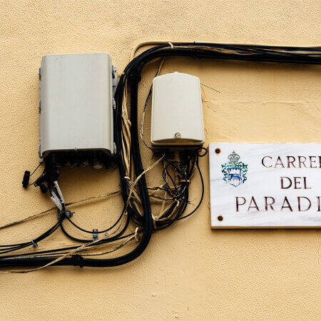
When laying wall-mounted optical cables in short straight segments (usually less than 10 meters), a fastening method is often used. The optical cable is typically secured using steel nail clips, with each clip fastening one cable.
8. Cable Raising
When transitioning from underground cable installation methods (direct burial, pipeline) to above-ground methods (overhead, wall-mounted), it is often necessary to raise the optical cable. Cable raising points are typically positioned against utility poles or walls. The portion of the optical cable within 2 meters above the ground usually requires protection using steel or plastic pipes, as shown in Figure 22.
9. Indoor Optical Cable Installation
Indoor optical cable installations are commonly seen, and the methods are similar to the installation of other indoor cables. Indoor optical cables are mainly laid using cable trays and conduits, as shown in Figure 23. They can also be installed within the ceiling.
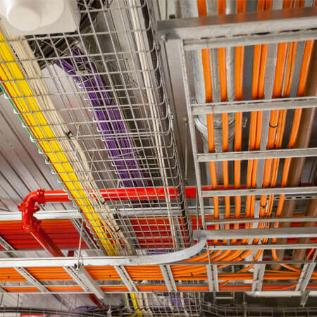
Indoor optical cables should be flame-retardant. After passing through holes in floors or walls, it is essential to tightly seal the holes using fireproof sealing materials.
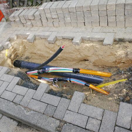
10. Shallow Burial of Optical Cables
According to existing regulations, direct burial of optical cables should use buried cables, and the burial depth in ordinary soil should exceed 1.2 meters. This standard is not necessary or practical for drop cables, especially those for terminal access. In practical engineering, shallow burial is often used for terminal access optical cables. This involves protecting a standard optical cable with a plastic conduit and burying it approximately 0.2 to 0.3 meters below the ground surface, as shown in Figure 24.
11. Conclusion
The above are common installation methods for communication optical cables. I hope they have been helpful to you.