We know that increasing the baud rate speeds up the transmission of symbols through the channel, but can lead to increased signal attenuation. Increasing the pulse amplitude modulation scheme (PAM) allows more bits to be sent per symbol, but with lower error margins and tighter thresholds.
The international organizations IEEE and OIF have both moved to define 800G and 1.6T on 224Gb/s lines. Below are a few of the challenges and potential solutions for implementing 800G and 1.6T (based on 224Gb/s channel rates).
1. Switch Silicon SerDes
Faster network switching chips are critical to increasing channel speeds. High-speed application-specific integrated circuits (ASICs) enable low-latency switching between components in server racks and data centers. From 2010 to 2022, switch silicon bandwidth increases from 640Gb/s to 51.2Tb/s through multiple improvements in complementary metal oxide semiconductor (CMOS) process technology.
SerDes (serializer/deserializer) speed and the number of SerDes (I/O pins) define the bandwidth of the chip. For example, a chip with a bandwidth of 51.2Tb/s has 512 10Gb/s SerDes, which is enough to support 400G Ethernet capacity with 128 ports, each consisting of four 100Gb/s channels. The next generation of switch silicon will again double the bandwidth, with 102.4T switches having 512 channels of 200Gb/s SerDes. These silicon switches will support 800G and 1.6T through 224Gb/s channels.
2. Pulse Amplitude Modulation
Increasing the symbol rate (baud rate) results in signal degradation because the data moves faster through the channel. Maintaining the signal integrity of high-speed digital communications becomes more complex, so standards organizations have adopted higher modulation schemes to increase the number of bits per symbol. For example, 400G Ethernet uses four-stage Pulse Amplitude Modulation (PAM4) SerDes to increase the data rate from 50Gb/s to 100Gb/s at the same symbol rate of 50GBd. With this change, 400G networks can begin using four channels of 100Gb/s instead of eight channels of 50Gb/s.
Pulse amplitude modulation requires tradeoffs. Sending more bits per cycle reduces the noise margin per symbol. With non-return-to-zero (NRZ) signaling, the voltage threshold range to distinguish between zero and one bit is higher. As the number of bits per symbol increases, the threshold gets smaller and the noise immunity decreases. Under 50 GBd NRZ conditions, the noise level does not close the eye diagram, which means that the receiver can clearly distinguish the bit level, but this can be problematic for receivers trying to interpret 50 GBd PAM4 symbols.
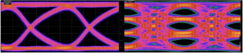
PAM4 signals have a smaller eye diagram height and therefore have smaller design margins for noise and jitter.
For now, the industry may retain the generality of PAM4 and move on to other methods of maintaining data integrity at high speeds. However, future standards may utilize higher modulation schemes (PAM6 or PAM8).
3. How Does Forward Error Correction Reduce BER?
In most high-speed data standards, fine-tuned equalizers in the transmitter and receiver compensate for signal degradation in the channel by ensuring that signals transmitted over the channel can be interpreted at the other end. However, as rates push further beyond their physical limits, more sophisticated methods are required.
One such solution is forward error correction.
Forward error correction involves transmitting redundant data to help the receiver piece together signals that may have corrupted bits. Forward error correction algorithms usually recover data frames well when random errors occur, but they do not work well for burst errors where the entire data frame is lost.
Losing an entire data frame makes it more difficult for the receiver to reconstruct the signal. For example, a 224Gb/s transceiver requires a more robust FEC algorithm to successfully send and receive data. Each FEC architecture has tradeoffs and advantages in terms of coding gain, overhead, delay, and energy efficiency.
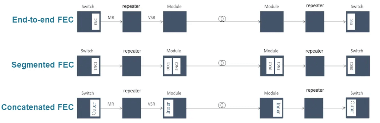
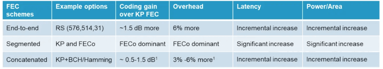
Although FEC helps mitigate the effects of random errors between the transmitter and receiver, burst errors can still cause problems. In 224Gb/s systems, more sophisticated FEC algorithms must be used to minimize burst errors. Test and measurement developers are developing FEC-aware receiver test solutions to recognize when frames are lost and to aid in debugging.
4. How do optical modules affect energy efficiency?
Perhaps the most serious challenge facing data centers is power consumption, or electricity consumption. Data centers consume approximately 1% of the world’s total power generation. Data center operators are looking to increase processing power without a corresponding increase in power consumption, and optical modules are one of the key components for improving energy efficiency.
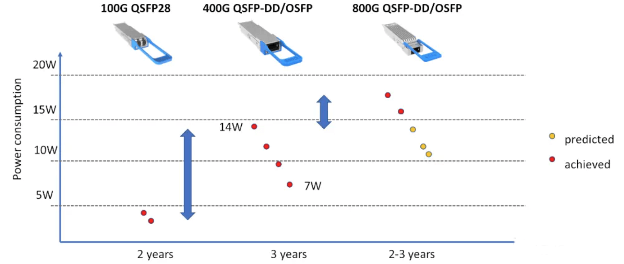
We understand that the power consumption of optical modules is increasing with each generation. For example, 100G pluggable modules (QSFP28) consume less than 5W, but 400G QSFP-DD modules consume up to 14W.
Of course, as optical module designs mature, they will become more energy efficient. The 800G QSFP-DD module, for example, debuted at 17 W; as the technology matures, power consumption should drop to 10 W. In general, power consumption is dropping with each Bit. However, with an average of 50,000 optical modules per data center, the increasing average power consumption of the modules remains a problem.
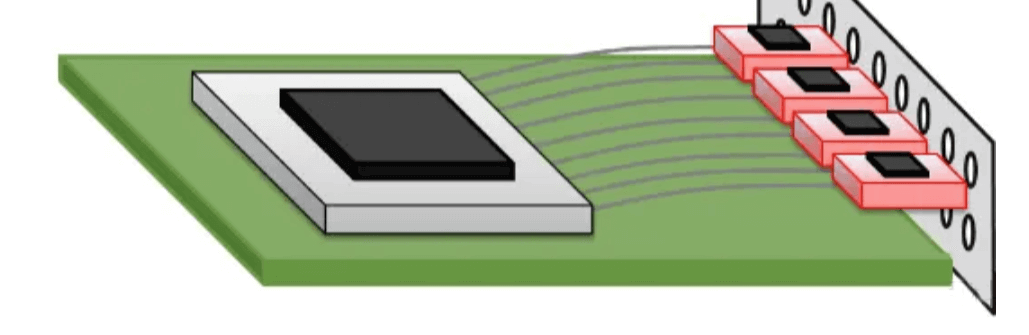
In order to improve energy efficiency, researchers are working on new packaging solutions, CPO co-packaged optics (Co-packaged) has the potential to achieve the lowest power consumption. Co-packaged optics move the optical module to the ASIC, eliminating the need for an optical retimer, and perform the photovoltaic conversion within the package. The trade-off here is that power dissipation is concentrated within the ASIC package, which may require new cooling solutions.
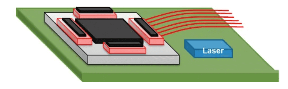
Cooling is another important power consumption factor in data centers. Co-packaged optics are in development, so the industry will likely continue to use pluggable optics in 800G systems. subsequent versions of the 800G or 1.6T standard may use co-packaged optics.
5. What Is The Timeline For The 800G And 1.6T Networks?
While it is impossible to accurately predict the future, we can make some observations based on the current state of network development. 2022 sees the final release of the OIF’s 112Gb/s standard and the IEEE’s 802.3ck (400G) standard. These standards will lay the groundwork for defining 800G over the 112Gb/s channel.
Over the next two years, the IEEE and OIF will finalize the physical layer standards and make additional announcements about co-packaged optics, 1.6T transceivers, and 224 Gb/s SerDes switching silicon, which will lay the groundwork for the final validation of 800G and 1.6T over 224 Gb/s channels.
Currently, 400G is being deployed at scale. Operators will upgrade hyperscale data centers to support the current wave of demand. By 2025, we may see 448Gb/s SerDes chips (using 102.4T ASICs) on the market. By then, we may be talking about 3.2T of network demand.