Loss budget analysis involves evaluating the anticipated loss performance of a fiber optic cabling setup. This article aims to provide you with a comprehensive introduction to the fundamental concepts, criteria, variables essential for conducting your own loss budget analysis and FAQs.
Criteria & Factors for Calculating Fiber Optic System Performance
Designing a fiber optic system involves finding a balance among various elements. Setting performance criteria and understanding the key factors that affect the system’s capability are essential. Remember, a fiber optic system is an amalgamation of its individual components.
To assess a system’s overall performance, a multitude of factors come into play. Here’s a basic rundown of elements crucial for determining the general transmission system performance.
- Fiber Loss Factor: Fiber loss holds significant sway over system performance. Manufacturers provide a fiber loss factor in dB per kilometer. Total fiber loss is calculated by multiplying the distance by the loss factor, considering the actual cable length.
- Fiber Type: Single-mode fibers have a loss factor ranging between 0.25 dB/km (@1550nm) and 0.35 dB/km (@1310nm). Multimode fibers exhibit around 2.5 dB/km (@850nm) and 0.8 dB/km (@1300nm). Fiber type matters, as multimode fibers work well with low-power L.E.D. transmitters, while single-mode fibers pair with LASER transmitters of varying outputs.
- Transmitter: Fiber optic systems use two primary transmitter types: LASER and L.E.D. LASER transmitters offer high, medium, and low outputs, matching system design. L.E.D. transmitters, compatible with multimode fibers, have a “high-power” version for single-mode fiber. Transmitters are rated in terms of light output, like -5dB.
- Receiver Sensitivity: Fiber optic receivers require a minimum amount of received light to function within specs. Receiver sensitivity is rated as the minimum required received light, e.g., -28dB.
- Splice Quantity & Type: Splices can be mechanical or fusion. Mechanical splices calculate around 0.7 to 1.5 dB per connector. Fusion splices are more preferred with losses between 0.1 and 0.5 dB per splice due to their efficiency.
- Margin: Building a system isn’t just about reaching the receiver with minimal light. The margin factors in fiber aging, component aging, additional devices, cable path dynamics, and more. Most designers include a 3 to 10 dB margin in the loss budget for flexibility and reliability.
Understanding these factors helps ensure a well-calibrated and high-performing fiber optic cabling system.
Calculating a “Loss Budget”
In the realm of fiber optic transmission systems, grasping the concept of a “loss budget” is essential. Let’s walk through a common scenario to shed light on this crucial aspect.
Scenario:
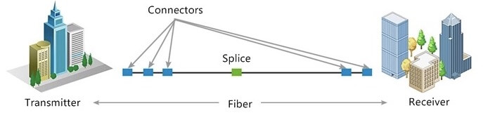
Imagine two operational centers situated approximately 8 miles apart as per the map. These centers boast wide area network capable routers with fiber optic communication link modules as their main communication devices. The centers are seamlessly connected by a fiber optic cable. Upon physically measuring the route, the actual distance, accounting for slack coils, turns out to be 9 miles. Notably, there are no extra devices installed along the cable route at present. Furthermore, future plans include integrating a freeway management system communication link within the next 5 years.
Important Points:
- For the sake of simplicity, all distance measurements will be converted to kilometers.
- Fiber cable usually comes in reels with a maximum length of 15,000 feet (equivalent to about 4.5km).
- Converting 9 miles, which is around 46,000 feet or 14.5km, is crucial. This system is anticipated to feature a minimum of 4 mid-span fusion splices.
By dissecting this real-world scenario, we can unlock the concept of calculating a “loss budget,” a fundamental step in ensuring the optimal performance of fiber optic communication systems.
| Fiber Loss Budget Calculation | |
| Fiber Loss | 14.5 km × 35dB =5.075 |
| Fusion splice Loss | 4 × 0.2dB =0.8 |
| Terminating Connectors | 2 × 1.0dB =2.0 |
| Margin | 5 |
| Total Fiber Loss | 12.875 |
| The manufacturer of the router offers three transmitter/receiver options for single mode fiber | ||
| Reach | Transmit Power | Receiver Sensitivity |
| Short | -3dBm | -18dBm |
| Intermediate | 0dBm | -18dBm |
| Long | +3dBm | -28dBm |
| To determine the correct power option add the transmit power to the fiber loss calculation | |||
| Reach | Transmit Power | Fiber Loss | Loss Budget |
| Short | -3 | -12.875 | -15.875 |
| Intermediate | 0 | -12.875 | -12.875 |
| Long | 3 | -12.875 | -9.875 |
| Compare this to the receiver sensitivity specification | |||
| Reach | Receiver Sensitivity | Loss Budget | Difference |
| Short | -18 | -15.875 | 3 |
| Intermediate | -18 | -12.875 | 6 |
| Long | -28 | -9.875 | 19 |
Since we factored in a 5.0dB loss margin in the fiber loss calculation, the short reach option will offer ample capacity for this system. Interestingly, the overall margin actually stands at 8.0dB, as there’s a 3.0dB difference between the loss budget and receiver sensitivity.
FAQs about Calculating Fiber Optic Loss Budget
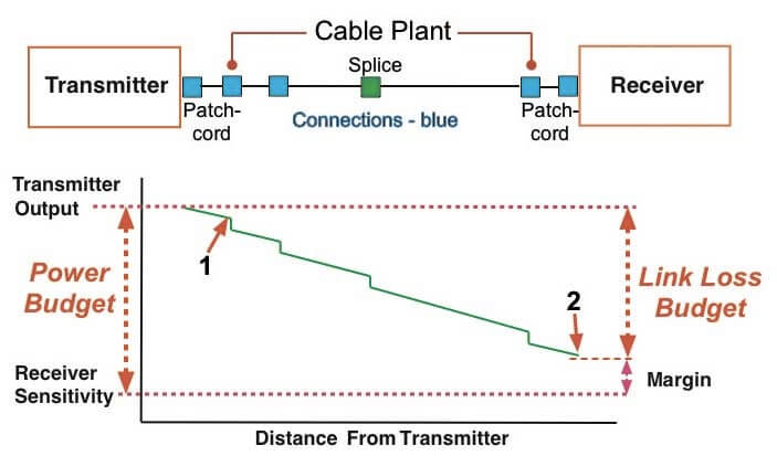
Q: What is the distinction between Link Budget (Power Budget) and Link Loss?
A: Link budget, also known as power budget, signifies the permissible level of signal loss a data link (transmitter to receiver) can endure while maintaining proper operation. It often includes both a maximum and minimum value to ensure the receiver’s input power stays within its functional range.
On the other hand, link loss budget pertains to the allowable magnitude of signal loss within a cable plant. It is computed by summing up the losses across all components used in the cable plant to estimate the end-to-end loss. Notably, the link budget and link loss budget are interconnected. A data link functions correctly when the link loss falls within the link budget’s scope.
In essence, link loss ≤ link budget for proper functionality; otherwise, optimal operation may be compromised.
Q:How to Calculate the Link Budget?
A: Calculating the link budget for optical transmission involves considering four key factors: minimum optical transmitter power, maximum connector insertion loss, optical fiber cable transmission loss, and maximum optical receiver sensitivity.
Transmitter Power and Receiver Sensitivity: These values are absolute, often measured in milliwatts (mW) or decibel milliwatts (dBm) using the formula 10*log(mW) = dBm.
Connector Insertion Loss and Optical Fiber Cable Transmission Loss: These values are relative, typically represented as percentage loss. Connector insertion loss accounts for various connections like fiber optical jumpers, transceivers, and patch panels.
To better understand link budget calculations, let’s explore a typical example: a 2-kilometer multimode link with 5 connections (2 connectors at each end, 3 connections at patch panels) and a central splice. Considering multimode fiber’s parameters—maximum fiber loss of 3.5 dB/km and a maximum acceptable connector insertion loss of 0.75 dB—the typical splice loss for multimode fiber is 0.3 dB.
In this scenario, the maximum link loss is estimated at 11.05 dB. This calculation aids in assessing the performance and viability of the optical transmission link. Keep in mind that link budget analysis is essential to ensure effective functioning of optical communication systems.
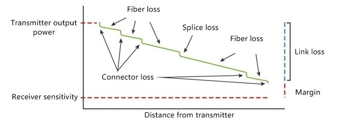
Q:How to Calculate the Link Loss?
A: Link loss is determined by considering several factors contributing to signal attenuation in a fiber optic link. The calculation can be represented as follows:
Link Loss = [fiber length (km) x fiber attenuation per km] + [splice loss x # of splices] + [connector loss x # of connectors] + [safety margin]
Let’s illustrate this with an example: Assume a single-mode link of 40 km at 1310nm with 2 connector pairs and 5 splices.
Link Loss = [40 km x 0.4 dB/km] + [0.1 dB x 5] + [0.75 dB x 2] + [3.0 dB] = 21.0 dB
In this scenario, an estimated link loss of 21.0 dB indicates the amount of power needed to effectively transmit across this link. It’s crucial to remember that actual link loss values should be measured and verified once the link is established to ensure optimal performance and identify potential issues.
Q: Does the Speed of the Optoelectric Transceiver Affect the Link Budget?
A: Yes, the speed of the optoelectric transceiver does impact the link budget. Generally, slower link speeds provide more tolerance for signal loss. However, advancements in technology have led to improved laser power and receiver efficiency in newer transceiver generations. This means that some of the most efficient systems can also operate at higher speeds.
Q: Does Temperature Affect the Link Budget?
A: Yes, temperature can impact the link budget. Some components can operate within wider temperature ranges without failure. However, all components tend to be less efficient at higher temperatures due to less effective electrical conversion. Lower temperatures can also affect light sources differently based on their type. Generally, component manufacturers provide min/max values that account for temperature effects.
Q: Does Cable Type Impact Link Loss?
A: Yes, the type of cable used does affect link loss. Multimode cables generally introduce more loss compared to single-mode cables. Single-mode cables have fewer issues with dispersion but are more sensitive to bending. Regardless of cable type, all cables inherently introduce some level of loss, with each type having a rated loss per distance segment. Shorter links typically mitigate the impact of cable type.