What is PLC splitter?
PLC stands for Planar Lightwave Circuit. PLC splitter is an integrated waveguide optical power distribution device based on a quartz substrate. Like the coaxial cable transmission system, the optical collection system also needs to couple, branch, and distribute the beams, which requires an optical splitter to achieve.
PLC splitter is one of the most important passive devices in optical fiber links. It has multiple input ends and multiple output fiber optic tandem devices, and is especially suitable for connecting central offices in passive optical networks (EPON, GPON, BPON, etc.) and terminal equipment, and realizing the branching of light signals. The number of branches available are: 1×2, 1×4, 1×8, 1×16, 1×32, 1×64, 2×2, 2×4, 2×8, 2×16, 2×32, 2×64. Connectorized PLC splitters can be used with common fiber optic connectors such as LC/SC/FC/ST.
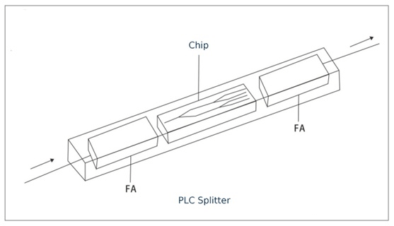
PLC splitter manufacturing technology
PLC optical splitter consists of an optical splitter chip coupled with fiber arrays at both ends. This technology is made by semiconductor technology (lithography, etching, development, etc.), and the optical waveguide array is located on the upper surface of the chip, the splitting function is integrated on the chip, that is, the multi-channel equal division of the output end is realized on one chip. Then, the multi-channel fiber arrays of the input end and the output end are respectively coupled at both ends of the chip and packaged. Its production process includes coupling alignment, packaging, optical testing and reliability testing. The process is stable and consistent, the loss is not related to the wavelength of light, the channel uniformity is good, and the structure is compact and small in size.
According to manufacturing technology, there is another type of splitter. That is FBT splitter. Click to learn if you want to know more about the differences between FBT splitter and PLC splitter.
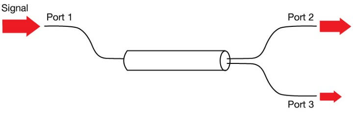
How does PLC splitter work?
PLC splitters are based on planar lightwave circuit technology. It consists of three layers: substrate, waveguide and cover. The waveguide plays a key role in the splitting process that allows a specific percentage of light to pass through, so the signal can be equally divided. In addition, PLC splitters are available in a variety of split ratios, including 1:4, 1:8, 1:16, 1:32, 1:64, and more.
PLC splitter function
- Developed using quartz glass waveguide circuits and aligned fiber pigtails integrated in a miniature package.
- Distribute or combine optical signals based on planar lightwave circuit technology.
- Provides a low-cost solution for optical signal distribution with a very small form factor and excellent reliability.
- Provides a better solution for applications that require larger split configurations. To achieve this, the waveguides are photolithographically fabricated into silica glass substrates, which allow a specific percentage of light to be split. Therefore, the PLC splitter provides accurate and uniform light splitting with minimal loss of optical power.
The main advantages of PLC splitters
- All-band type (1260~1650nm), insensitive to wavelength.
- Good spectral uniformity, good loss-consistency at each output end, low polarization-related loss, high reliability and stability; low failure rate.
- There are many splitting channels for a single device, which can reach more than 64 channels.
- The structure is compact and the volume is small, and it can be directly installed in various existing terminal boxes and transfer boxes without the need to leave a large installation space.
- Multi-channel cost is low, and the more branches, the more obvious the cost advantage.
The main disadvantages of PLC splitters
- The device manufacturing process is complex.
- Compared with the FBT splitter, the unit cost is higher, especially for the low-channel splitter.
Classifications of PLC splitters
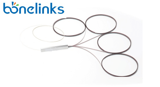
- Bare Fiber Optical Splitter
The bare fiber splitter is the simplest and most commonly used PLC optical splitter in FTTX projects, this type of PCL splitter has fiber left on all ends. Therefore, network engineers can splice freely according to the application. At the same time, the bare-fiber PCL splitter requires only a small amount of space during the wiring process. Therefore, it can be installed in the optical fiber splicing box to provide distributed signals for FTTH.

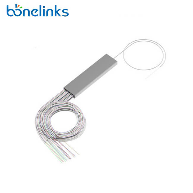
- Blockless PLC optical splitter
A blockless PLC optical splitter looks like a bare fiber splitter. The main difference from bare fiber splitters is that blockless PLC splitters use a compact stainless steel tube package, usually terminated with fiber optic connectors.

- Plug-in PLC optical splitter
The plug-in PLC optical splitter is a widely used FTTx project, especially in the distribution of FTTx network users. In places that has limited space, the plug-in PLC optical splitter provides quick installation and facilitates FTTx project deployment. - ABS cassette PLC optical splitter
ABS cassette PLC optical splitter uses a plastic box to hold the splitter chip. The input fiber and output fiber are on a layer of split waveguide made of a silica substrate, which provides easier and more flexible routing. In addition to providing reliable protection, the ABS box PLC optical splitter can also be installed in various wiring cabinets or chassis. It is very common to install an ABS cassette PLC optical splitter in a standard 19″ rack unit. - Fanout PLC optical splitter
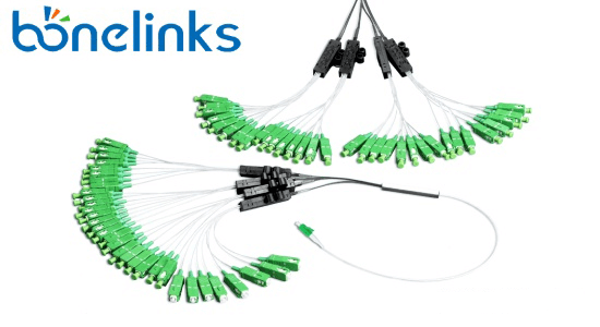
Fanout PLC optical splitter generally uses 0.9mm tight-packed optical fiber, which increases the length of the branched ribbon optical fiber connected to the PLC chip. The adapter of this optical splitter has a variety of split ratios, which can meet the requirements of users who need different types of splitters.
- LGX cassette PLC optical splitter
The LGX box-type PLC optical splitter looks like an MTP distribution box, which puts the entire PLC optical splitter in a metal box, and isolates the distribution fiber embedded in the panel and the input fiber of the fiber optic adapter. LGX PLC optical splitters can be installed individually or in standard rack units or fiber enclosures for better wiring. - Tray PLC optical splitter
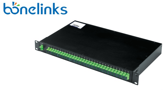
The tray-mounted PLC splitter uses a space-saving package for better cable management. However, it adopts an international 19-inch design to deploy in ODF for good cable management and signal transmission. The design clearly marks the ports of the tray-type PLC optical splitter, which can reduce the failure caused by the wrong connection. - Rack-mounted PLC optical splitter
Rack-mounted PLC optical splitters are designed to meet the requirements of high-density data centers or server rooms. It can be securely mounted on a data center or server rack. Multiple ports can be added to the PLC optical splitter, which is an ideal solution for high-density wiring.
Application of PLC Splitter
PLC splitter is widely used in FTTH, PON, CATV, LANs, and other optical communication systems to realize splitting/combining functions.
It is the first choice for connecting OLT and ONU in the optical access network and realizing optical power distribution. WDM-PON networks will use arrayed waveguides instead of splitters. With the rapid development of FTTx worldwide, the need for large splitter configurations in the network is also growing. Due to performance benefits and overall deployment cost, PLC splitters are now the ideal solution for FTTx applications.
How does PLC splitter work in the PON network?
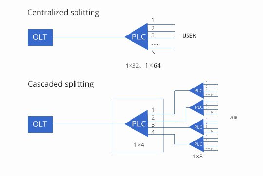
In the PON network, the PLC optical splitter mainly has two optical splitting configurations: centralized splitting and cascaded splitting.
PLC optical splitters used in fiber distribution hubs include tray PLC splitters, plug-in PLC splitters, and ABS box PLC splitters, and PLC splitters used in fiber optic terminal boxes including bare fiber PLC splitters and so on.
- Centralized splitting
The centralized splitting of PLC optical splitters means that the optical splitters are centrally installed at a certain position between the optical line terminal (OLT) and the optical network unit (ONT), and the signals at the central office are concentrated and processed, and then transmitted to each end user respectively. It is more suitable for network applications where users are more concentrated. The split ratios of the PLC optical splitters used are usually 1:32 and 1:64.
Cascaded splitting
The biggest difference between centralized splitting and cascaded splitting is that the cascade has two-level splitting (the centralized has only one-level splitting). The following figure is an example of delivering network services to 32 home users through the cascade splitting of PLC optical splitters. From the figure, we can see that the splitting ratio of the first-level optical splitter is 1:4, and the splitting ratio of the second-level optical splitter is 1:8.
The cascade method is more complex than the centralized splitting of PLC optical splitters, but it can maximize the use of optical fiber resources, and the wiring is flexible, which is more suitable for network applications where users are scattered.
 How to choose an optic splitter?
As a simple passive component, PLC splitter evenly divides an input optical signal into multiple output optical signals and can support many users to share a single network interface.
If you want to learn more about know how to choose, please click here.
At the end
The above is the introduction to the PLC splitter. Hope it is helpful to you. Bonelinks mainly produces and sells optical transmission equipment and accessories for the communication industry, we provide various types of PLC splitters with different packages, splitting ratios, and connectors, etc. If you have any needs, please contact us, Bonelinks is here to serve you.