| Fiber Cable Type | Multimode 48 Cores |
|---|---|
| Fiber Type | |
| Connector Type | |
| Fiber Count | 48 Fiber |
| Fiber Cable DIA (mm) | 7.0 |
| Pre-terminated Connector | MPO |
| Connector Endface | UPC |
| Operating Wavelength (nm) | 850 |
| Fiber Type | OS1 |
| Cable Color | Yellow |
| Cable Jacket | LSZH |
| Length (m) | From 0.5 to 15 |
| Output Length (m) | From 0.5 to 15 |
| Temperature Range | __header |
| Installation | -40℃ to 70℃ (-40°F to 158°F ) |
| Operation | -40℃ to 85℃ (-22°F to 185°F ) |
| Storage/Transport | -40℃ to 85℃ (-40°F to 185°F ) |
| Mechanical Properties | __header |
| Insertion Loss (dB) | Typical Values≤0.3; Max Values≤0.35 |
| Polarization-related losses (dB) | Typical Values≤0.1; Max Values≤0.2 |
| Mating (times) | Max Values≤0.2; ≥1000 |
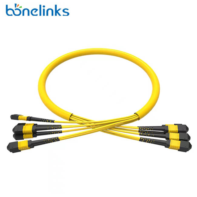
MPO Trunk Cable
Trunk fiber optic patch cable MPO to MPO, as the name suggests, is designed to be laid in the telecommunications room in the backbone network line, and used to connect the data transmission between the cabinet and the cabinet of a multi-core branch cable.
Usually, the structure of MPO to MPO trunk fiber optic patch cable is relatively simple, mainly consisting of MPO connector and trunk cable. Since MPO trunk cable is the bridge between cabinet and cabinet or between cabinet and equipment, it is necessary to identify the link connection methods between transceivers to determine the polarity of MPO branch patch cable. MPO to MPO branch cable production process, first, choose to cut different cores of fiber optic cable; then extract a certain length of fiber cores in the cable, peel off the coating layer and cladding layer, in order to insert the assembled MPO connector, and then through curing, grinding, light to complete the installation of MPO connector end. At the other end of the cable, follow the same steps as above to pre-terminate the MPO connector, then the whole branch cable patch cord can be produced.
After the whole patch cable is assembled and produced, it does not mean that the product can be used off-line. Then needing to test if the MPO connector end face is clean, whether all channels can pass light transmission signal, whether attenuation value meets the required standards, if 3D test meets the standard. When any of the test data is abnormal, the whole jumper needs to be reworked or even re-produced. When all the functional test items are completed, the test report will be affixed to the bag of each patch cable one by one to show Bonelinks’ quality assurance.
Related products
- Fiber Optic Patch Cord
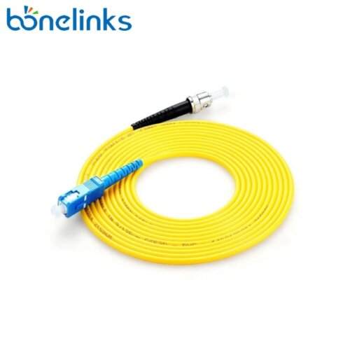
SC to ST Fiber Patch Cable
- Fiber Optic Patch Cord
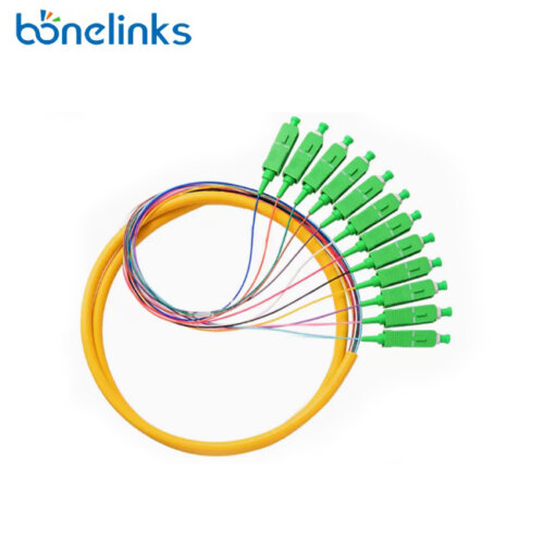
12 Color Pigtail
- Fiber Optic Patch Cord
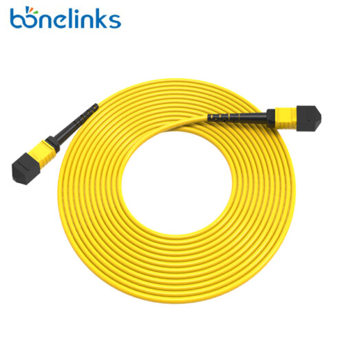
OS1 MPO to MPO Fiber Patch Cord