
FTTH Structure Overview
Not all FTTH networks are built in the same way. While network construction and outdoor devices occupy most network cost, choosing suitable FTTH structures are making a great impact on commercial cases. Network structure may influence future possibilities of updating, network performance and final customer satisfaction.
The aritical will make a brief overview of two FTTH structure categories (Centralization Structure and Cascaded Structure). These two structures decide optical fiber beam split at the network. Fiber optical splitter placement and split ratio will make a huge influence fiber patch cord’s placement and quantities, which will FTTH network deployment costs finally.
Centralization Structure or Cascaded Structure
PON is basic fiber optical construction at FTTH network. Fiber Optical splitter should be the first consideration at deciding what kinds of PON structure. Centralization structure adopts central hub’s single stage splitters at star topology while cascaded adopts multi-stages splitters at tree branch topology.
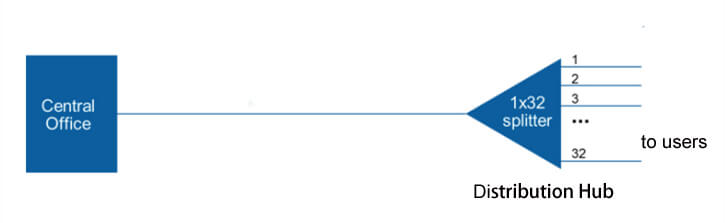
Centralization structure usually adopts 1×32 splitters at FDH. Splitters can be placed everywhere. Input cable from splitter connects to central office GPON OLT directly. Output cables will connect to 32 families ONT through patch panel, splicing conjunction. Therefore, PON connects one OLT port and 32 ONT.
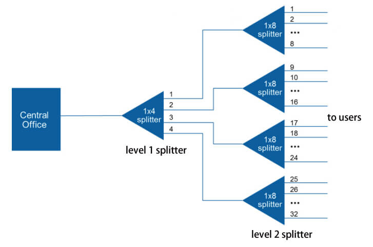
Cascaded structure may adopt 1×4 splitter at the outdoor cabinet. The splitter connects to central office OLT port directly, 4 output cables connecting level 2 1×8 splitters. Under this deployment, 32 fibers (4×8 splitters) can access to 32 families. Cascaded structure contains 2 levels splitters and optical beam split-change.
Centralization structure is flexible to reduce operation costs and maintenance in the future while cascaded structure can generate returns at the fastest time and reduce secondary costs as well as fiber maintenance costs. There needs to specify these structures’ advantages and disadvantages before deployment. More cases will be shown to distinguish cascaded structure and centralization structure similarities and differences.
Fiber Distribution Hub (FDH) Centralization Structure
This structure not only utilizes optical fiber splitters efficiently and improves network access at most but simplifies troubleshooting and reset device speed.
FDH centralization structure, usually, starts from inner 1×32 splitters. Separated 32 fibers will connect to 32 families ONT by patch panel connecting, fiber optical splicing and point to point conjunction.
Although optical fiber splicing provides high flexibilities at network installation and lowers fiber attenuation at most, there needs higher labor costs and time to deploy and maintain devices. Almost all network has to splice for optical conjunction.
As for pre-terminated solutions, factories will assemble connectors that are designed for harsh environments to meet fast deployment and lower installation costs. FDH can be equipped with connectors (HMFOC) to connect 12 cores OSP cable at distribution network. FDH and terminal pigtail can be inserted into splitters to provide integrity pre-terminated connection structure.
Adopting FDH centralization method at pre-terminated solution have lots of attractive advantages including deployment speed, long-term flexibility and more functions in the future. Utilizing splitters connectors also can strengthen network access. If a certain area cannot guarantee a network adoption rate, under further development, adoption will be increased gradually. FDH centralization structure is suitable for such area network deployment.
Optical Fiber Splice Closure Centralization Structure
Central data center trunk cables connect fiber optical closure which contains splitter at distribution point under this centralization structure. Under this situation, FDH is for distribution while the closure is for splicing. Though closure’s main function is just for splicing conjunction, it can be equipped with splitters to realize expected network deployment. More closures can be deployed at the secondary level to expand the network.
There needs to lay optical fiber trunk cable from central hub to the closure then splicing to splitters. Splitters output cable will extend to other closures. This structure is designed for small network distribution because just needs a few closures and splitters.
While closures at centralization structure need to splice inner fibers, device maintenance cost is extremely low at first. With time passing by, its flexibilities and maintenance costs will gradually grow up. All in all, one main closure and 2 subsidiary closures will cover small area.
Optical Fiber Splice Closure Cascaded Structure
Trunk cable from central office gets access to the closure and passes by the first 1×4 splitter (see picture). Output fibers, then, get access to users next small closure or access terminates. At each smaller closure, distribution fibers will connect to next splitter. Lastly, each unit from buildings or families will connect to those splitters’ output ports to achieve the whole network conjunction.
Adopting optical fiber closure cascaded structure, usually, splice fibers within central closure then to joint splicing fibers into splitters’ input. There is to say, trunk cable will splice to connect splitter’s input then distribute fiber to connect splitter’s output. Splitters input may equip connectors and adapters at factories, this half splicing half pre-terminated installation is popular at cascaded structure networks. Remote area or high adoption rate area is suitable for adopting this deployment method.
Cascaded Optical Multiplexing Architecture
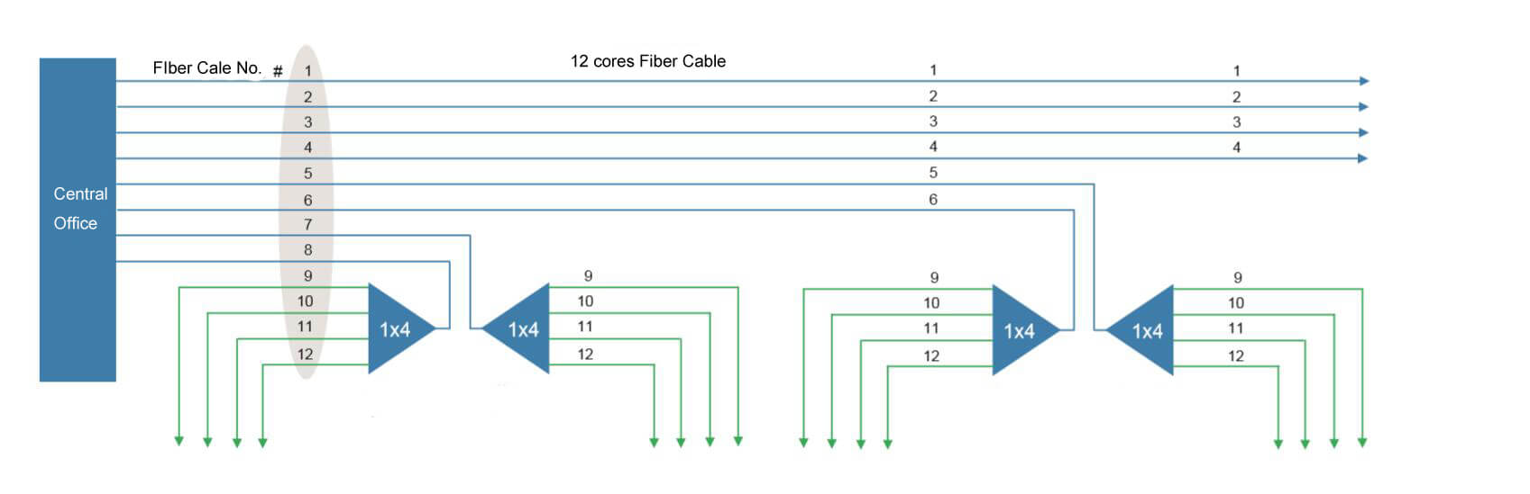
This structure is based on cascaded structure equipping a very high utilization rate. 1X32 optical beam split and 12 cores trunk cable at the service area will take as samples to explain this structure.
There is one cable used to trunk cable and distribution fibers. 1 to 8 fibers are trunk cable fibers, each fiber from central office connects to level 1 service area splitter directly. 9 to 12 fiber will be distribution fiber connecting level 1 splitter and level 2 splitter. Those distribution fibers will be separated into several parts to service certain area networks. While distribution fiber 9 to 12 do not connect to central office directly, they will be reused in a certain area.
Each trunk cable will be separated at level 1 1×4 splitter, then separated at level 2 1×8 splitter. These fanout cable connect to users directly, providing network services for 32 families. Therefore, combining trunk cable and breakout functions, 12 cores cable can service up to 256 families.
Cascaded optical multiplexing architecture takes effect in large rural or MDU environments. All parts including accessories are small, which will make few influences on the environment or building aesthetics.
There needs attention that cascade optical multiplexing structure design, construction, recording, and maintenance cost are large. But fiber optical utilization rate is high and closure cost is lower.
Conclusion
The aritical introduces some common centralization and cascaded FTTH architecture. At each deployment project, user’s expectations, construction plan, and environment are unique. Realizing each structure’s advantages and disadvantages will help to choose suitable architecture for fiber optical cabling.