Optical cable lines lightning protection and strong current protection are achieved by avoiding, guiding or discharging them underground to prevent lightning and strong current from causing damage to the optical cable lines themselves, communication equipment and personnel.
Since the lightning protection and strong current protection measures for optical cable lines are often unified, they are often considered together in projects.
General Requirement
In the annual average number of days of thunderstorms greater than 20 days in the region and the history of lightning strikes, fiber optic cable lines should be used to prevent lightning measures.
Thunderstorm hazardous areas, the new fiber optic cable lines should be avoided around the isolated large trees, towers, towering buildings, street trees, woods and other easy to attract lightning targets. When it can not be avoided, should be used arc extinguishing line, can be used non-metallic fiber optic cable.
Fiber optic cable joints on both sides of the metal components should not be electrically connected, should not be grounded.
For Direct Buried Fiber Optic Cables
Newly built silicon core pipes or direct buried fiber optic cables with metal components should be set up according to the soil resistivity (ρ10) at a depth of 10m to provide a lightning protection line (also known as “discharge line”).
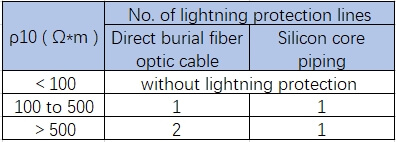
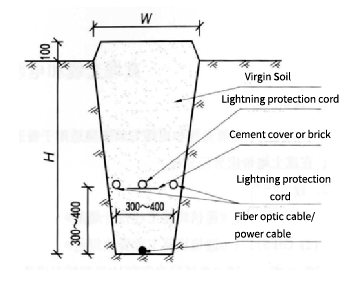
Lightning protection line should be 7/2.2 galvanized steel stranded wire, and fiber optic cable, silicon core plastic pipe vertical interval should be 300mm.
Single lightning protection line should be located in the fiber optic cable, silicon core plastic tube is above, double lightning protection line between the interval should not be less than 300mm, and should not be greater than 600mm.
Lightning protection line should not be less than 2km length of continuous deployment.
For Aerial Fiber Optic Cables
1. Anti-strong electricity
Poles and power supply lines above 35kV shall be crossed vertically, and when they cannot be crossed vertically, the minimum angle of crossing shall not be less than 45°.
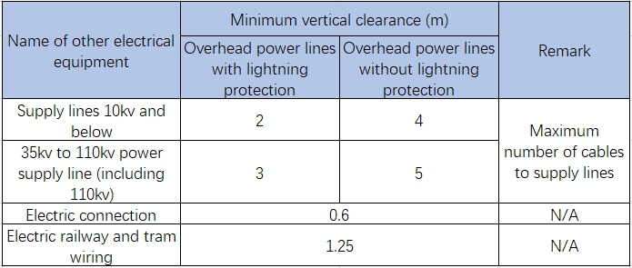
The minimum vertical clearance between aerial fiber optic cables and commonly used electrical facilities shall meet the requirements of the following table.
When the overhead fiber optic cable crosses the overhead power supply line, it should be set up under the power supply line.
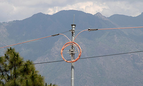
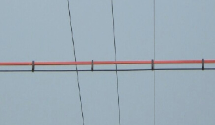
Crossing part of the overhead line should be used to protect the three-wire protection insulation deck or protection sleeve fixed in the stranded wire for protection, the length of the protection beyond the edge of the two sides of the crossing each 1m, as shown in the following figure.
When the power supply line is a covered line, the fiber optic cable can also be crossed over the line.
When the overhead fiber optic cable crosses the high-voltage power supply line above 10kV, the hanging wires on the overhead fiber optic cable poles on both sides of the crossing file should be grounded, and the ground wires on the poles should be disconnected from the ground at a height of 2.0m with a 50mm discharge gap, and the pulling wires on the poles on both sides of the crossing file should be equipped with insulators at a height of 2.0m from the ground and should be set up with an electrical disconnect.
The hanging wires on the nearby poles on both sides of the crossing gear shall be retrofitted with insulators and shall be electrically disconnected.
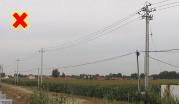
The horizontal clearance between the newly erected pole and the power supply line should be not less than 4/3 of the height of the pole, and it is strictly prohibited to erect the pole directly under the power supply line.
2 Lightning protection
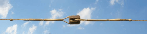
Every 250m or so poles, terminal poles, corner deeper than 1m corner poles, flying line across the pole, pole length of more than 12m poles, poles on the top of the hill should be set up lightning conductor, overhead suspension line should be connected with the ground.
The suspension line should be every 300m ~ 500m using the pole lightning conductor or cable grounding, every 1km or so should be installed insulators to set the electrical disconnect.
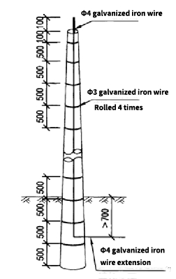
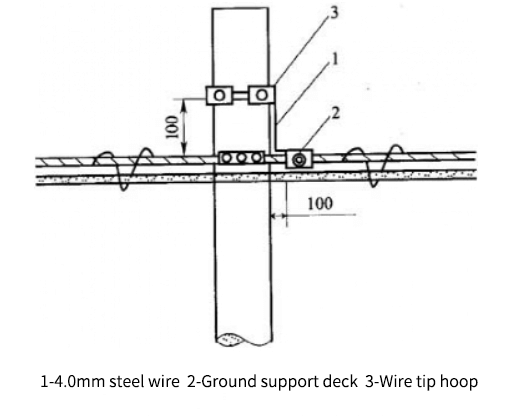
The use of pulling wire as a lightning conductor, 4.0mm steel wire (also known as “galvanized iron wire”) one end should be 100mm above the pole, 100mm from the top of the pole should be 3.0mm steel wire bundled, and every interval of 500mm bundled once, the other end of the 4.0mm steel line pressed into the cable hoop and its good contact.
The other end of 4.0mm steel wire should be pressed into the hoop and in good contact with it. 4.0mm steel wire should be fastened with nails on the wooden pole, and the spacing of the nails should be 500mm.

Cement poles without reserved lightning conductor spikes should use 4.0mm steel wires as lightning conductors throughout the whole process, and put them into the ground along the poles, as shown in above the figure.
Cement poles with reserved lightning conductor nails should be connected with the reserved nails by 4.0mm steel wires.
When the hanging line uses the pulling wire to make the ground, the hanging line should be connected to the pulling wire hoop with 4.0mm steel wire through the ground clamping plate, and enter the ground through the pulling wire.
When there is no pulling wire to be utilized, the ground wire on the pole can be laid along the pole, and the ground wire on the pole can be 4.0mm steel line or steel stranded line, and the suspension wire is put into the ground through the ground wire on the pole.
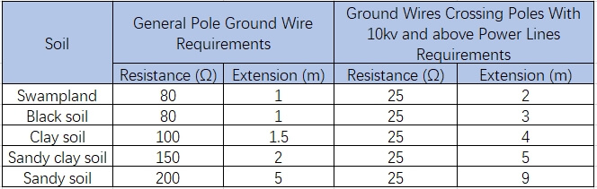
The underground extension of the ground wire on the pole should be buried in the ground below 700mm, can be “serpentine” extension, is strictly prohibited coil.
The grounding resistance and extension length of the extension line should meet the requirements of the following table.
Fiber Optic Line Termination Grounding
ODF racks of high-voltage protective devices should be used cross-sectional area of not less than 35m㎡ copper-core power cable lead to the first level of grounding sinks in the room, access to the room’s ODF racks can also be used cross-sectional area of not less than 16m㎡ copper-core power cables led to the floor of the room where the grounding row on the nearest.
The high-voltage protection device of the outdoor fiber optic cable conjunction box should be connected to the grounding device by a grounding wire with a cross-sectional area of not less than 16m㎡.
The fiber optic cable distribution box installed outdoors can be grounded with a ground rod, and the fiber optic cable distribution box and the ground rod can be connected by a 4.0mm steel wire.
The fiber optic cable distribution box installed in the urban area does not have good conditions for installing the ground wire, and it does not need to be grounded, but the optical cable entering the fiber optic cable distribution box should be insulated from the ground.
Optical cable junction boxes, optical cable distribution boxes, and optical cable terminal boxes installed indoors should directly use the steel bars in the building foundation as the grounding body, or use multi-strand copper wires with a cross-sectional area of not less than 16mm2 to connect to the existing grounding device.
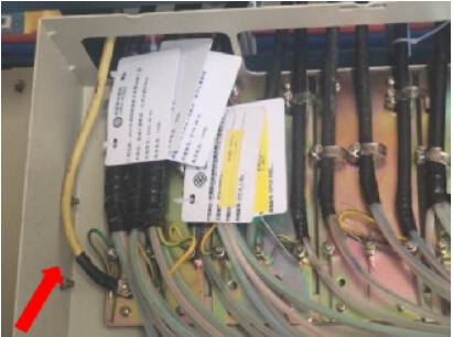
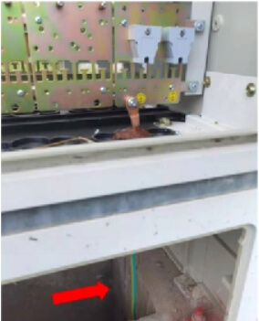
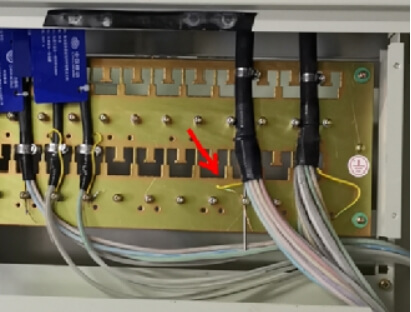
In the ODF, optical cable junction box, and well-grounded fiber distribution box, the outdoor optical cable should use a multi-strand copper core wire with a cross-section of not less than 6m㎡ to reliably connect the metal components of the optical cable to the high-voltage protective grounding device, as shown in the figure below.
The metal components of the indoor optical cable should be electrically disconnected from the ODF, the high-voltage protective grounding device of the optical cable junction box, the rack, and the box.
Final Thoughts
In the current technical standards for communication line projects, the lightning protection and strong current protection of optical cable lines mostly follow the previous protection measures for overhead wires or cable lines.
Some protection measures are too strict for optical cable lines but have little practical significance. For example, the grounding resistance of the optical cable junction box is required to be no more than 10Ω. However, in actual projects, insufficient attention is often paid to the dangerous impact of strong current, resulting in electric shock accidents during the construction of optical cable lines.
Bonelinks recommend to further study the lightning protection and high-voltage protection measures for optical cable lines, and make some revisions in a timely manner according to the characteristics of optical cable lines and changes in high-voltage line construction standards. If you have a better way to protect fiber optic cables from lightning or strong electricity, please feel free to contact us at bonelinks.com and let us know.