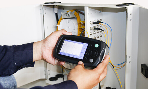
OTDR (Optical Time Domain Reflectometer) is an important equipment for fiber optic line quality inspection and fault location by using Rayleigh scattering and backscattering generated by Fresnel reflection when light is transmitted in optical fiber.
Under the control of precise clock circuit, it transmits optical pulse signals to the optical port according to the set parameters, and then the OTDR continuously receives the light signals reflected back from the optical fiber from the optical port according to a certain time interval, and carries out the corresponding tests on the optical fiber in accordance with the principles of Rayleigh backscattering (to test the loss of the optical fiber) and Fresnel reflection (to test the reflection of the optical fiber) respectively.
Therefore, OTDR is widely used in the maintenance and construction of fiber optic cable lines to measure fiber length, fiber transmission attenuation, connector attenuation and fault location.
OTDR combines a laser light source and a detector to provide an inside view of a fiber optic link. When the laser light source sends a signal carrying a certain amount of energy into the fiber, the detector receives light reflected from different elements of the link in the fiber. The properties of the fiber are known when a clock accurately calculates the time it takes for the pulse to propagate and then converts the time to distance.
As the pulse travels along the fiber, a small portion of the pulse energy returns to the detector due to reflections from the link and the fiber itself. When the pulse returns completely to the detector, a second pulse is sent – until the end of the sampling time. Thus, the OTDR immediately performs multiple samples and averages them to provide a clear characteristic map of the link elements.
At the end of sampling, signal processing is performed and the OTDR calculates distance, loss and reflection for each event in addition to total link length, total link loss, optical return loss (ORL) and fiber attenuation.

What Is Rayleigh Backscattering
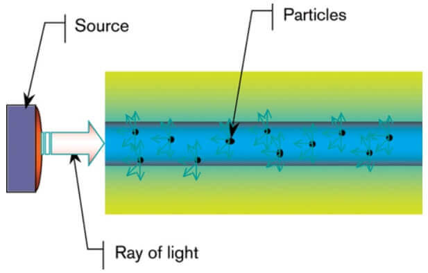
Originating from the reflection and absorption of tiny particles or inhomogeneous structures inside the fiber, when light is irradiated on the impurities, some particles redirect the light to different directions, which at the same time produces signal attenuation and backscattering.
The magnitude of the loss is inversely proportional to the 4th power of the wavelength, i.e., as the wavelength increases, the loss decreases rapidly. A point in the fiber backward echo can reflect the distribution of optical power in the fiber, according to which you can test the loss of the fiber.
Loss: Rayleigh Backscatter = 5Log (P0 × W × S) – 10ax (loge)
P0: transmitted optical power (W)
W: transmitted pulse width (s)
S: reflection coefficient of the fiber (W / Joule)
a: attenuation coefficient of the fiber (nanojoule / m)
1 nanojoule = 8.686dBx: fiber distance
Rayleigh backscattering is used as a function of distance to calculate the attenuation level (in dB/km) in an optical fiber and is shown as a straight line slope in the OTDR trace. This phenomenon arises from the reflection and absorption inherent in the impurities within the fiber.
When light strikes the impurities, some of the impurity particles redirect the light in a different direction, producing both signal attenuation and backscattering. The longer the wavelength, the less attenuation there is, and therefore the less power required to transmit the same distance over a standard fiber.
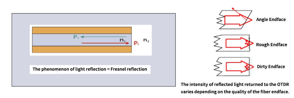
What Is Fresnel Reflection
The second type of reflection (Fresnel reflection) used by OTDRs detects physical events along the link. The reason for this is that when light reaches a location where there is a sudden change in refractive index (e.g., from glass to air), a large portion of the light is reflected back, resulting in Fresnel reflection, which can be thousands of times stronger than Rayleigh backscatter.
Fresnel reflection can be recognized by spikes in the OTDR trace. Examples of reflections with such a location are connectors, mechanical splices, optical fibers, and broken fibers or open fiber connectors.
A Few Of The Parameters Used In OTDR
1. Test Distance
As the refractive index of the optical fiber is basically unchanged after the manufacture of its refractive index, so that the propagation speed of light in the optical fiber is unchanged, so that the test distance and time is the same, in fact, the test distance is the propagation speed of light in the optical fiber multiplied by the propagation time, the selection of the test distance is the test of the sampling start and termination time of the selection.
Measurement of the appropriate test distance can generate a more comprehensive trajectory map, effective analysis of the characteristics of the fiber is very helpful, usually based on experience, select the entire optical path length of 1.5-2 times the most appropriate.
The distance can be calculated by taking the time taken from the emission of the pulse to the reception of the reflected pulse, and then determining the speed of propagation of the light in the optical fiber.
2. Pulse Width
It can be expressed in terms of time or in terms of length. It is obvious that, in the case of a constant magnitude of optical power, the magnitude of the pulse width directly influences the magnitude of the energy of light, the longer the optical pulse the greater the energy of light.
At the same time, the size of the pulse width also directly affects the size of the test dead zone, which also determines the shortest distance between two recognizable events, i.e., the resolution. Obviously, the smaller the pulse width, the higher the resolution, the larger the pulse width the lower the resolution.

3. Refractive Index
It is the actual refractive index of the optical fiber to be measured. This value is given by the manufacturer of the optical fiber to be measured, and the refractive index of a single-mode quartz fiber is about 1.4-1.6.
The more precise the refractive index is, the more helpful it is to improve the accuracy of distance measurement. This issue also has practical guidance for the configuration of optical routing, in fact, in the configuration of optical routing should be selected refractive index of the same or similar fiber configuration, minimize the different refractive index of the fiber core connected together to form a non-single refractive index of the optical path.
4. Test light wavelength
That is, the wavelength of the laser emitted by the OTDR laser, the shorter the wavelength, the stronger the Rayleigh scattering of the optical power, the higher the trajectory generated in the receiving section of the OTDR, so the 1310nm pulse generated by the Rayleigh scattering of the trajectory pattern than 1550nm to produce a higher pattern.
However, in the long-distance test, due to the 1310nm attenuation, the laser pulse issued by the laser at the end of the fiber to be tested will become very weak, so affected by the noise is greater, the formation of the trajectory is not ideal, it is appropriate to use 1550nm as the test wavelength.
In the high wavelength region (above 1500nm), Rayleigh scattering will continue to reduce, but an infrared attenuation (or absorption) will be generated, so 1550nm is a wavelength with the lowest attenuation, and therefore suitable for long-distance communication. Therefore, it is suitable to select 1550nm as the test wavelength for long-distance testing, while 1310nm is suitable for ordinary short-distance testing, depending on the specific situation.
5. Average value
In the OTDR to form a good display pattern, according to the user needs dynamic or non-dynamic display of the fiber condition and set the parameters.
Due to the influence of noise in the test, the Rayleigh scattering power of a point in the fiber is a random process, to know the general condition of the point, to reduce the influence of random noise inherent in the receiver, you need to ask for its average value in a certain period of test time.
Set the value according to the need, if the requirement of real-time grasp of the situation of the fiber, then you need to set the average time of 0, and look at a permanent optical path, then you can use an infinite time.
6. Dynamic range
Dynamic range is an important OTDR parameter. This parameter reveals the maximum optical loss that can be analyzed by the OTDR when dropping from the backscatter level of the OTDR port to a specific noise level, i.e., it determines the longest fiber distance that can be measured by the OTDR. In other words, this is the maximum fiber length that can be reached by the longest pulse. Therefore, the greater the dynamic range (in dB), the longer the distance that can be reached.
Indicates the power loss ratio between the onset of backward scattering and the noise peak. If the dynamic range of the OTDR is small and the fiber to be tested has a high loss, the far end may disappear into the noise. There are two methods of defining dynamic range:
1,. Peak method: it measures the peak of the noise, when the scattered power reaches the peak of the noise is considered invisible.
2. SNR = 1 method: here the dynamic range is measured until the rms level of the noise, for the same performance of the OTDR, its indicators are higher than the peak definition of about 2.0db.
7. Backward scattering coefficient
If the backward scattering coefficients of the two fibers connected are different, there is a high probability that the fiber under test is a gainer on the OTDR. This is due to the fact that the scattering coefficient at the back end of the connection point is greater than the scattering coefficient at the front end, which results in the optical power reflected back from the back end of the connection point being higher than that reflected back from the front instead. Encountering this situation, it is recommended that you use a two-way test of the average interest value of the approach to the measurement of this fiber.
8. Dead zones
The dead zone is caused by the reflection flooding the scattering and saturating the receiver, and is usually divided into two cases: attenuation dead zone and event dead zone.
(1) Attenuation dead zone: The distance from the point of reflection until the point of reception returns to a backscatter level within about 0.5 db. This is the point where OTDR can test attenuation and loss again.
(2) Event dead zone: from the OTDR received reflection point to the OTDR recovery of the highest reflection point 1.5db a bit of this distance, here you can see whether there is a second reflection point, but can not test attenuation and loss.
Tips For Using OTDR
1. Simple judgment of fiber quality
Under normal circumstances, the OTDR test of the body of the light curve (single drum or several drums of fiber optic cable) slope is basically the same, if a section of the slope is larger, it indicates that the attenuation of this section is larger; if the body of the curve is irregularly shaped, with a large undulation of the slope, bending or arcing, then it indicates that the quality of the optical fiber is seriously degraded, does not meet the requirements of the communication.
2. Wavelength selection and unidirectional and bidirectional testing
1550nm wavelength test distance is farther, 1550nm than 1310nm fiber is more sensitive to bending, 1550nm than 1310nm unit length attenuation is smaller, 1310nm than 1550nm measured fusion splicing or connector loss is higher.
In the actual maintenance of fiber optic cable work generally on both wavelengths are tested, compared. For the positive gain phenomenon and more than the distance line are required to carry out two-way test analysis and calculation, in order to obtain a good test conclusion.
3. Fiber optic connector cleaning
Before fiber optic connectors are plugged into the OTDR, they must be carefully cleaned, including the output connector of the OTDR and the connector under test, otherwise the insertion loss is too large, the measurement is unreliable, the curves are much noisy or even make the measurement impossible, and it may also damage the OTDR.
Avoid cleaning agents other than alcohol or refractive index matching solution as they can dissolve the adhesive inside the fiber optic connector.
4. Correction of refractive index and scattering coefficient
In the case of fiber length measurements, each 0.01 deviation in the refractive index can cause an error of as much as 7 m/km, and for longer sections of light, the refractive index values supplied by the fiber optic cable manufacturer should be used.
5. Recognition and treatment of ghosting
Spikes on the OTDR curve are sometimes echoes caused by reflections that are close to the incident end and are strong; such spikes are called ghosting.
Identification of ghosting: no significant loss is caused at the ghosting on the curve; the distance between the ghosting and the beginning of the curve is a multiple of the distance between the strong reflection event and the beginning of the curve, in a symmetrical shape.
Eliminate ghosting: Choose short pulse widths and add attenuation to the strongly reflecting front end (e.g., OTDR output). If the event causing the ghosting is at the fiber termination, a “”small bend”” can be made to attenuate the light reflected back to the beginning.
6. Treatment of positive gain phenomena
Positive gain phenomenon may occur in the OTDR curve. Positive gain results from the fact that the fiber after the fusion point produces more backward scattered light than the fiber before the fusion point.
In fact, the fiber is fused with fusion loss at this fusion point. It often occurs in the fusion splicing process of fibers with different mode field diameters or different backward scattering coefficients, so it is necessary to measure in both directions and average the results as this fusion splicing loss. In the actual maintenance of fiber optic cables, can also be used ≤ 0.08dB is qualified for the simple principle.
The Main Factors For Test Errors In OTDRs
1. Inherent bias in OTDR test instruments
As can be seen from the testing principle of OTDR, it sends optical pulses to the measured optical fiber at a certain period, and then samples, quantizes, and encodes the backscattered signal from the optical fiber at a certain rate, and then stores and displays it.
OTDR instrument itself due to the sampling interval and the existence of error, this inherent bias is mainly reflected in the distance resolution. OTDR distance resolution is proportional to the sampling frequency.
2. Errors arising from improper operation of test instruments
In fiber optic cable fault location testing, the correctness of the use of OTDR instrumentation is directly related to the accuracy of the obstacle test, the instrument parameter setting and accuracy, improper selection of the range of the instrument or inaccurate setting of the cursor will lead to errors in the test results.
(1) Setting the refractive index of the instrument deviation generated by the error
The refractive index of different types and manufacturers of optical fibers is different. When using OTDR to test the length of optical fiber, it is necessary to set the instrument parameters first, and the refractive index setting is one of them.
When the refractive index of several sections of fiber optic cable is different, you can use the method of segment setting to reduce the testing errors caused by refractive index setting errors.
(2) Improper selection of the range
OTDR instrument test distance resolution of 1 m, it is the graphic enlargement to the horizontal scale of 25 m / grid to achieve. Instrument design is to move the cursor every 25 steps for 1 full frame.
In this case, the cursor moves 1 meter for every step, so the reading resolution is 1 meter. If the horizontal scale is chosen to be 2 kilometers/per frame, the distance is shifted by 80 meters for every step the cursor moves. This shows that the larger the range selected for the test, the greater the deviation of the test results.
3. Improper selection of pulse width
Under the condition of the same pulse amplitude, the larger the pulse width, the larger the pulse energy, at which time the dynamic range of the OTDR is also larger, and the corresponding blind zone is also larger.
4. Inappropriate choice of averaging time
OTDR test curve is to sample the reflected signal after each output pulse, and do the average processing of multiple samples to eliminate some random events, the longer the averaging time, the closer the noise level is to the minimum value, the greater the dynamic range. The longer the averaging time, the higher the test accuracy, but when it reaches a certain level, the accuracy is no longer improved. In order to improve the test speed and shorten the overall test time, the general test time can be selected within 0.5~3 minutes.
5. Improper placement of the cursor
Fiber optic connectors, mechanical splices, and breaks in the fiber can cause losses and reflections, and the ruptured end face at the end of the fiber can produce a variety of Fresnel reflection peaks or no Fresnel reflections due to the irregularities of the end face. If the cursor is not set accurately enough, it will also produce some error.
Summarize
As there are many OTDR instruments available in the market ranging from basic fault finders to multifunctional tests that can fulfill different test and measurement needs. When shopping for an OTDR, it is important to consider the basic parameters, test requirements to make the right choice.
Selecting a device based on overall performance and price alone can be problematic if the model selected is not suitable for the application. OTDRs have complex specifications, most of which are compromises. Understanding the functional parameters of an OTDR and verifying them first will help to make the right choice to meet the needs and maximize productivity and cost-effectiveness. If you have any other questions, feel free to contact us.