In FTTH and other broadband fiber optic access engineering design, it is necessary to calculate the attenuation of the ODN fiber optic link according to the corresponding wavelength of the application system, on the one hand, to verify whether it meets the requirements of the system’s optical power budget index, on the other hand, as a reference index for engineering acceptance.
ODN Fiber Optic Link Attenuation Calculations
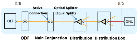
The entire attenuation of an ODN fiber link refers to the attenuation between the S/R and R/S reference points in the fiber link from the OLT to the ONU.
A common reference model for ODN fiber link attenuation is shown in the figure below, which usually includes: fiber and fixed connection attenuation Af, optical splitter insertion loss As, active connection insertion loss Ac, and additional loss Aa.
In the design, the calculation of ODN optical fiber link attenuation should adopt the worst value calculation method, that is, the relevant indicators adopt the technical indicators in the standards, specifications or bidding documents, rather than the actual typical indicators (the average value of the corresponding product indicators of first-tier manufacturers).
For example, in the relevant standards, the attenuation indicator of active connections is 0.5dB/unit (any two connectors of the same model are interconnected), and the typical indicators of manufacturers’ products generally do not exceed 0.25dB/unit, so they should be recorded as 0.5dB/unit when calculating.
Optical Fiber And Fixed Connection Attenuation Af
Fiber and fixed connection attenuation Af includes fiber attenuation and fixed connection attenuation. Fiber attenuation = Fiber attenuation coefficient (dB/km) × Fiber length (km). The fiber attenuation coefficient is related to the wavelength used by the system.
The typical values of the fiber attenuation coefficient at the upstream and downstream wavelengths of GPON and XG-PON are shown in the figure below.

Fixed connection is relative to active connection, including mechanical splicing connection and fusion splicing connection.
Mechanical splicing connection is mainly used for on-site termination of optical drop cables. On-site termination has poor stability.
With the popularization of portable fusion splicers, it has gradually been replaced by fusion splicing termination.
The average attenuation indicators of optical fiber fixed connections are shown in the table below.

In ODN, it is usually difficult to know how many fiber connectors are included in the entire fiber link, and the attenuation of fiber fusion is also very small in the attenuation of the entire fiber link. Therefore, when calculating, the attenuation of the fiber and the attenuation of the fusion are often combined to simplify the calculation.
The reference values of fiber and fusion attenuation per kilometer are shown in the following table. When there are both single core connectors and fiber ribbon connectors in the link, the average value of single-core splicing and fiber ribbon splicing is taken.
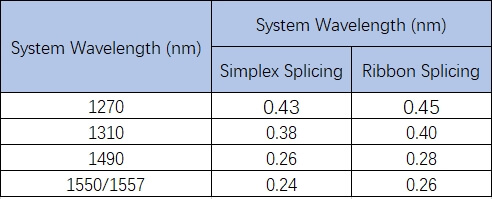
The optical fiber and fixed connection attenuation Af can be calculated by multiplying the reference value in Table 2 by the length of the optical fiber link. When the link includes cold connections, the cold connection loss can be calculated separately at 0.1dB/connector.
Optical Splitter Insertion Loss As
Equal-ratio splitting is mainly used in ODN. Depending on the connection method, the equal-ratio splitter is mainly divided into two types: abs box type and plug-in type, as shown in the figure below.

ABS box type splitters are mainly used in optical cable junction boxes, and plug-in type splitters are mainly used in optical cable fiber distribution boxes.
The insertion loss increases by about 3dB for each increase in the split ratio of the splitter. For splitters with the same split ratio, the insertion loss of the plug-in splitter is about 0.2dB greater than that of the abs box splitter, as shown in the following table.

However, in FTTR, rural areas, and buildings, the application of unequal-ratio beamforming is increasing. The figure below is an ODN fiber link attenuation reference model for unequal-ratio beamforming in a building scenario.

The main types of unequal ratio optical splitters are 1×5 and 1×9.
The 1×5 splitter includes 1 cascade port and 4 branch ports, and the 1×9 splitter includes 1 cascade port and 8 branch ports. The insertion loss reference values of 1×5 and 1×9 splitters are shown in the table below.

Active Connection Insertion Loss Ac
In ODN optical fiber links, active connections are usually used at ODF, trunk optical cross-connection, and optical splitter. The insertion loss of active connections is calculated at 0.5dB/piece.
The insertion loss of a new active connector generally does not exceed 0.25dB/piece, but as the use time increases, due to end face contamination and other reasons, the insertion loss will increase to a certain extent. Calculating at 0.5dB/piece will not produce too much link attenuation surplus.
OLT, ONU and ODN also use active connections, but this active connection is not included between the S/R and R/S reference points and does not belong to the ODN optical fiber link.
Usually, each optical splitter has two active connections with the optical fiber link. However, according to the test principle of splitter insertion loss in YD 2000.1-2014, as shown in the figure below, the insertion loss value of the optical splitter already includes the insertion loss of one active connection. Therefore, when calculating Ac, only one active connection of each splitter needs to be counted.

Additional Loss Aa
In ODN, due to the irregular construction and maintenance, as well as the use of G.652 fiber pigtail termination in the home-entry optical cable, the ODN link often generates large macro bending losses.
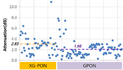
For example, the downlink attenuation test results of some home-entry optical cables in a certain city are shown in the figure below (each point in the figure represents a different user), among which the average attenuation of XG-PON users is as high as 2.85dB, and the average attenuation of GPON users is also 1.98dB.
Although the additional macro bending loss is mainly caused by non-standard construction and maintenance, it is difficult for operators to take effective measures to solve this problem.
Therefore, the additional loss caused by macrobending loss in ODN will exist for a long time. The additional loss Aa can be determined by referring to the following table.
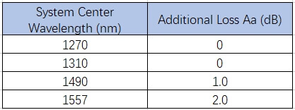
The additional loss of the ODN optical fiber link mainly occurs in the home section. When the ODN optical fiber link does not contain the home section optical cable line, the additional loss should not be recorded.
Calculation Example
According to the calculation method and related reference indicators described above, the full-length attenuation of the ODN fiber link with equal-ratio splitting and unequal-ratio splitting can be calculated as shown in the above figure.
When the ODN link is 5.0km long and the total split ratio is 1:64, the calculation of the full-length attenuation of the GPON downstream ODN link is shown in the table below.

It should be noted that when using unequal-ratio optical splitting, since the insertion loss of the branch port of the unequal-ratio splitter is more than 5.0 dB greater than that of the equal-ratio splitter with the same number of branches, when calculating the attenuation of the entire ODN link, the R/S point is usually taken at the ONU connected to the last unequal-ratio splitter at the far end of the link.
Put At The End
The attenuation calculation of ODN optical fiber links is not only applicable to the acceptance of FTTH and FTTx projects. When planning the regional network laying, the overall link node design and the purchase of passive ODN products that meet the attenuation requirements should be carried out according to the number of access users and the network uplink and downlink transmission rates. In this way, whether it is the initial link design stage or the completion stage, it can ensure that the link loss of the entire network is within the control range, providing guarantee for subsequent network operation and maintenance.