POTDR is a polarization optical time domain reflectometer. When an optical fiber is deformed, the polarization state of the light signal changes from the deformed position.
The principle technology of POTDR is based on the polarization properties of light and the scattering phenomenon. Light is composed of electromagnetic waves, which can vibrate in a specific direction, which is called the direction of polarization of light. In optical fibers, the presence of strain, temperature changes, or other forms of perturbation can cause a change in the direction of polarization of light. This change causes the scattering of light, which causes the energy of the light to be reflected back in the direction in which it was transmitted through the fiber.
POTDR takes advantage of this scattering phenomenon to analyze the distribution of strain, temperature, and other parameters in an optical fiber by measuring the intensity of the reflected light and the change in polarization state.
Specifically, POTDR sends modulated laser pulses into an optical fiber, then receives the reflected light and measures the changes in the intensity and polarization state of the reflected light. The time delay and polarization state of the reflected light can be obtained based on the light scattering phenomenon, and thus the distribution of parameters such as strain and temperature change in the optical fiber can be determined.
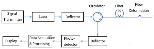
The system composition of POTDR is shown below. The light pulse emitted from the laser outputs the polarized light pulse signal through the polarizer, the light pulse enters into the optical fiber to be tested through the annular device, the light signal scattered and reflected from the optical fiber to be tested is output to the bias detector through the annular device, and then arrives at the photodetector, and the system does the data processing for the acquired signal and displays the detection results.
OTDR’s Shortcomings
OTDR (Optical Time Domain Reflectometer) is a commonly used instrument in fiber optic cable engineering and maintenance, is the use of optical signals transmitted in optical fiber Rayleigh scattering and Fresnel reflections, through the reflection curve to understand the loss distribution of optical fiber along the length of the fiber, you can measure the length of optical fiber, line attenuation, connector attenuation, and other items. It can also be used to locate fiber optic fault points.
However, OTDR often has the following problems when performing fault localization:
- It is difficult to locate quickly. For example, the OTDR finds that the fault point is 10.0km away from the test point, and the fault point is 870m away from the nearest optical closure, but it is very difficult to find the corresponding optical closure and then the corresponding fault point 870m away from the optical closure in the field, unless it is very obvious that the fiber optic cable at the fault point has been damaged in the field.
- It is difficult to find the target cable from a number of fiber optic cables. The same pole road, pipeline often laid dozens of fiber optic cables, it is difficult to find the target cable from a number of fiber optic cables.
The above two problems are easily solved by POTDR.
Application Of POTDR In Fiber Optic Cable Maintenance
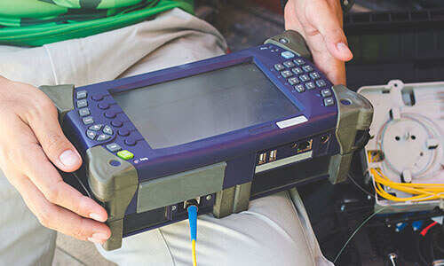
The following is an example of the application of POTDR in fiber optic cable line maintenance using a fiber optic cable network operation analyzer. The main functions of POTDR include fiber optic cable census, fault tracking, and OTDR test analysis.
1. Fiber Optic Cable Census
This function helps the user to quickly locate the target fiber optic cable from multiple fiber optic cables at the same location.
When using the fiber optic cable census function, two engineers and technicians are required: the meter operator and the fiber optic cable operator.
The device operator uses the meter to do the test at the ODF or fiber optic cable junction box, and the fiber optic cable operator bends the fiber optic cable at the location where the fiber optic cable census needs to be conducted. The two of them cooperate with each other, and identify the fiber optic cable through the audible indication of the buzzer of the meter and the display of the trace map.

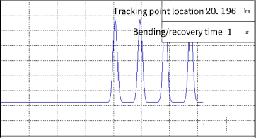
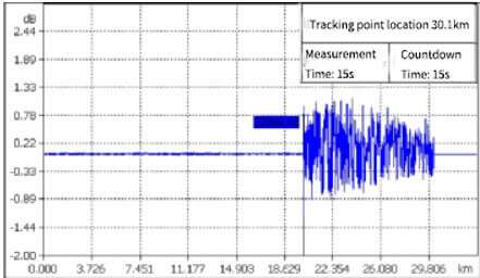
In the process of fiber optic cable census test, the fiber optic cable operator in accordance with the time length of 1 second on the fiber optic cable for the cycle of “bend/hold/release/hold” operation, if the instrument’s buzzer sounds, or traces displayed in the area of the trace map has a large spike, as shown in the figure below, it means that the fiber optic cable operated by the operator is the current test cable, the census was successful, otherwise, it means that the fiber optic cable operated by the operator is not the current test cable, the cable operator needs to replace another cable operation.
If the meter buzzer sounds or the trace line shows a large spike as shown in the figure below, it means that the fiber optic cable operated by the fiber optic cable operator is the current tested fiber optic cable and the census is successful.
2. Fault Tracing
The fault tracing function of the meter displays the distance of the fiber optic cable operator from the fiber optic fault point, so that the fault point can usually be found by no more than three traces.

When using the fiber optic cable tracking function, it is also necessary for the meter operator and the fiber optic cable operator to cooperate with each other.
When there are multiple cables in the route, the cable census should be used to find the target cable, then the cable operator keeps the cable stationary while the meter operator uses the meter’s Template Acquisition option to acquire the backward polarization curve.
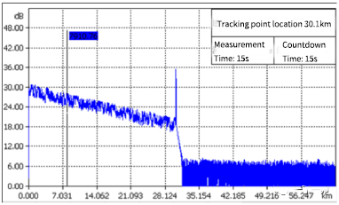
After that, the fiber optic cable operator bends the fiber optic cable as required and holds it still while the meter operator uses the meter’s Fault Trace option. The meter acquires the backward polarization curve again, compares it with the curve stored in the acquisition template, and returns the Fault Trace result. The meter displays the distance of the bend point from the origin (test point) and the distance from the fault point (tracepoint).
3. ODTR test
PODTR is developed on the basis of ODTR and naturally has the functions of ODTR. Compared with ordinary ODTR, CMDI’s fiber optic cable network operation analyzer has wifi connectivity, which allows it to connect with cell phones and use APP to control the terminal meter for testing, or uploading and sharing the test results.
Concluding Remarks
In conclusion, POTDR technology is a testing method based on fiber optic sensing, which realizes the measurement of physical quantities such as temperature and strain in optical fibers by using the scattering and polarization characteristics of optical fibers for optical signals.
It has the characteristics of high resolution, high sensitivity and remote measurement, and is widely used in fiber optic communication networks for fault location in fiber optic cables and quality inspection of fiber optic connections, in electric power systems to monitor the temperature and strain in transmission lines, to achieve remote monitoring and protection of electric power equipment, and also can be used to monitor the deformation and cracks in structural engineering such as bridges, tunnels and buildings, in order to improve the safety and stability of the structure, and so on.
Compared with ordinary ODTR, many network service providers currently lack understanding of POTDR, and the price of PODTR instrumentation is much higher, so the selection and procurement of equipment should first be considered according to the actual operation and demand, and then compare the functions of each model of equipment and warranty, etc., in order to maximize the use of POTDR in order to improve the efficiency of operation and maintenance on the basis of cost savings.