
The RFID system consists of electronic tags, readers, and background management software, as shown in the figure below.
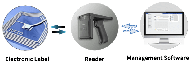
When in use, the reader sends a radio frequency signal, and the tag antenna generates an induced current after receiving the radio frequency signal to obtain energy, the circuit in the tag is activated, and the information stored on the chip is sent through the antenna. After receiving the information, the reader transmits the information to the background management software, and the management software manages the object identified by the electronic tag based on the received information.
Technical Characteristics of RFID
RFID is divided into low frequency (LF), high frequency (HF), ultra high frequency (UHF), and microwave (MW) according to the different application frequencies. The corresponding representative frequencies are: low frequency below 135kHz, high frequency 13.56MHz, ultra high frequency 860MHz~960MHz, microwave 2.4G, 5.8G (such as ETC).
RFID is divided into passive RFID, active RFID and semi-active RFID according to the energy supply method of the electronic tag.
Passive RFID has a short reading and writing distance and low cost.
Active RFID can provide a longer reading and writing distance, but it needs power supply and is more expensive. It is suitable for long-distance reading and writing (such as ETC).
Semi-active RFID electronic tags are usually in a dormant state, and only the basic circuit is maintained by the built-in battery. When entering the low-frequency (such as 125kHz) activation signal range, they are awakened and communicate with the reader through high frequency (such as 2.4GHz). They are suitable for long-distance identification but limited battery life.
Compared with paper tags, RFID has the following advantages:
1) Non-contact reading, even if the tag is covered (except for metal and liquid), it will not affect the reading;
2) The tag has strong environmental adaptability, is resistant to stains, vibrations, and impacts, and can be read normally even if the surface is worn;
3) The tag has a long lifespan, which can reach more than 10 years;
4) The data inside the tag can be repeatedly erased and written;
5) A large number of tags can be read quickly at the same time, and a tag can be quickly found from multiple tags.
RFID Label Storage Area
The circuit of the electronic tag is mainly composed of an antenna and a chip, as shown in Figure a). Depending on the application scenario, the antenna specifications of the electronic tag are also different, as shown in Figure b).
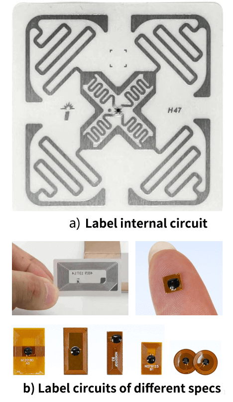
The small black dot in the middle of the circuit is a chip, which is about 0.5mm×0.5mm in size. The storage area of the tag chip is divided into four areas: password area, electronic code area (EPC), manufacturer code area (TID), and user area (User), as shown in the figure below.

There are two sets of 32-bit passwords in the password area, namely the access password and the kill password. The kill password can completely kill the chip.
The electronic code area is divided into three parts: the CRC part is 16 bits in total, which is responsible for verifying whether the EPC obtained by the reader is correct during communication; the protocol control (PC) part is 16 bits in total, which controls the length of the EPC; the EPC part is the electronic code of the chip, usually 64-496 bits, which can be written by the manufacturer or the user.
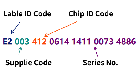
The manufacturer code (TID) is the most important identification of the chip and the only reliable code that accompanies its life cycle.
It includes an 8-bit tag type identification code (the tag type of all UHF RFID tag chips is E2), a 12-bit manufacturer code, a 12-bit chip model code, and a 64-bit serial number.
The 64-bit serial number can represent a number of 2 to the power of 64, which is already an astronomical number, so there is no need to worry about the problem of duplicate serial numbers of electronic tags. The following figure is an example of a TID expressed in hexadecimal.
The user storage area is usually 128 bits or 512 bits.
Current Status and Problems of Dumb Resource Management in Telecoms
Dumb resources refer to resources that cannot directly obtain network management information through electrical signals, such as poles, optical cables, junction boxes, fiber distribution boxes, ODF port resources, etc.
In communication networks, the number of dumb resources is very large. For example, by the end of 2024, the number of ODF port resources of a certain operator will exceed 5 billion (estimated based on the centralized procurement data released by the operator), and it is still growing at a rate of nearly 500 million per year.
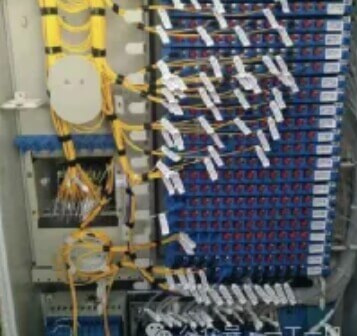
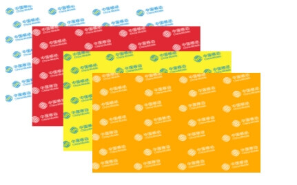
Dumb resource management has always been a headache for operators. Taking ODF port management as an example, ODF ports and jumpers are currently mainly marked by paper labels, as shown in the figure below. However, paper labels are easily damaged or lost, and are difficult to track and automate, which results in a low accuracy rate of ODF port resources in the asset management system.
Incorrect ODF port resources have a great negative impact on service deployment, engineering construction, and maintenance and repair. It is difficult to find the ODF port that needs to be jumped on site during service deployment, it is difficult to effectively utilize existing resources during engineering construction, and it is difficult to quickly determine the fault point during repair. Therefore, the effective management of dumb resources has become an important issue that operators have to face. In order to solve many problems in dumb resource management,
In recent years, RFID technology has begun to be used in some metropolitan area networks to manage dumb resources.
Dumb Resource Management System in Telecoms
A. Composition of dumb resource management system
The RFID-based dumb resource management system consists of electronic tags, readers, mobile phones and background management software, as shown in the figure below.
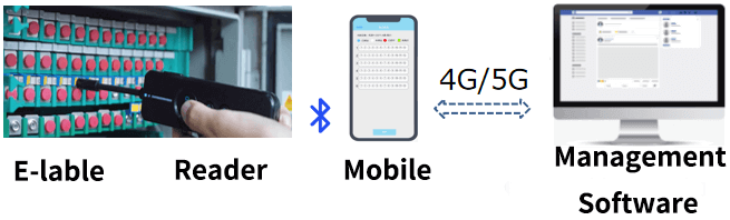
First, install electronic tags on dumb resources such as ODF ports and jumper fibers. When the electronic tag is read by a reader, the RF signal activates the tag, and the tag feeds back the TID to the reader. The reader is connected to the mobile phone via Bluetooth, and the TID is transmitted to the background management software via the mobile phone.
The background management software manages the corresponding dumb resources according to the TID. The mobile phone of the installation and maintenance personnel is responsible for the communication between the reader and the background management software, and is also the front end of the management software (on-site resource management is mainly completed through the app).
B. Electronic Label
Depending on the dumb resources identified, electronic labels include: ODF port labels, fiber jumper labels, optical cable labels, pole labels, manhole cover labels, etc.
(1) ODF port label
ODF port labels mainly include cover type and strip type, as shown in the figure below.
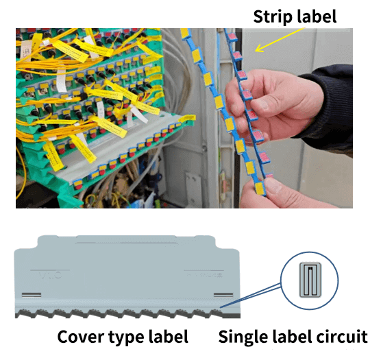
Both labels encapsulate a single label circuit of about 10mm×6mm in the position corresponding to the ODF port, which is equivalent to each ODF port label containing 12 single port labels.
During installation, the cover type port label can directly replace the cover of the original 12-core integrated tray in the ODF, and the strip type port label can be directly installed on the panel of the 12-core integrated tray.
(2) Patch fiber labels and optical cable labels
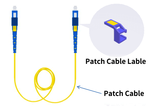
The patch cord labels are usually card sleeve type and are installed at both ends of the patch cord, as shown in the figure below. In the management software, the patch cord labels are generally linked with the ODF port labels to clarify the connection relationship between the ODF ports.
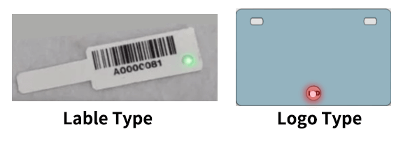
Optical cable electronic tags mainly include tape type and identification plate type, as shown in the figure below. Tape type electronic tags can be directly attached to the surface of the optical cable sheath, and the appearance and installation of identification plate type electronic tags are the same as traditional optical cable identification plates.
There is also a luminous label that flashes when activated, as shown in figure below. The packaging methods include a label type and an identification plate type, which can be used for identification of jumper fibers and optical cables, respectively.
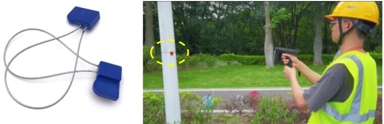
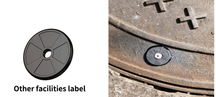
(3) Labels for poles and other facilities
The pole tag can be mounted on a pole as shown in the figure below.
Other facility labels can be used to identify manhole covers, junction boxes, computer rooms and other facilities, as shown in the figure below.
C.RFID Reader
There are two main types of readers used in dumb resource management, depending on the size of the antenna. One type has a very small antenna, which is connected to the reader body through a connecting rod, as shown in the figure below.

This type of reader is suitable for reading ODF port tags and tags installed at both ends of the jumper. When working, the reader antenna needs to be close to the tag (usually the reading distance does not exceed 5mm).
Another type of reader has a larger antenna and can be used to read tags on poles, optical cables, etc., or for group scanning (reading multiple ODF ports and jumper tags at a time). This type of reader has a longer reading distance, up to 5.0 meters.
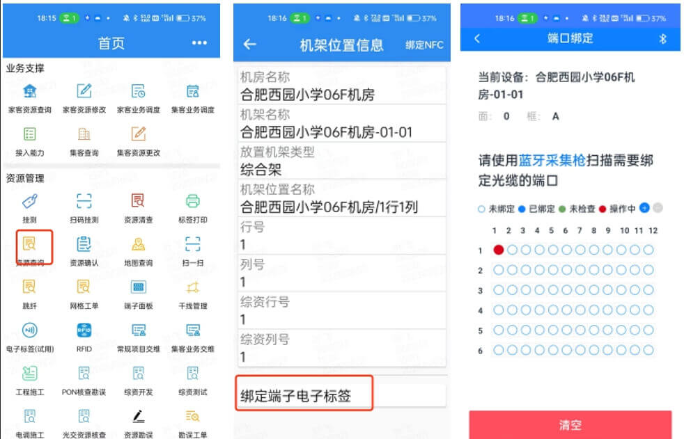
D. RFID Management Software
Management software is usually a subsystem of the pipeline resource management system, which is divided into the front end and the back end. The front end is the mobile app. The installation and maintenance personnel open the app at the installation and maintenance site and work with the reader, such as resource query, ODF port binding, resource errata, etc. Part of the operation interface of the app is shown in the figure below.
Conclusion
Although the RFID-based dumb resource management system can solve many problems in the existing optical communication dumb resource management, the current number of operators’ stock dumb resources is huge. If all of them are managed by RFID technology in the short term, the investment will be very huge. In addition, the accuracy of dumb resources still mainly depends on manual data collection and updating. The rationality of the management process will affect the accuracy of dumb resources and the efficiency of resource management. Therefore, RFID-based dumb resource management may not be achieved overnight, but should be a gradual process.
If you have a better RFID management method, please contact us for supplement.