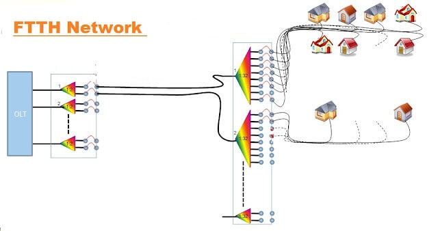
Optical splitter is one of the most important passive components in optical fiber links and plays an important role in FTTH passive optical networks. It is an optical fiber device with multiple input ends and multiple output ends, especially suitable for connecting the central office and terminal equipment in passive optical networks (EPON, GPON, etc.) and realizing the branching of optical signals.
With the wide application of FTTH network, in order to serve more users, PLC optical splitter has become the most popular optical splitter in FTTH applications due to its advantages of a large number of branches and uniform light splitting.
1. FTTH network splitting level
PON is the foundation of FTTH network, and optical splitter is an important part of the PON network. In the daily FTTH construction, the PON network structure can be designed as centralized splitting (one-level) and cascaded splittings (two-level or more) according to the structure of the community and the distribution of buildings. The different splitting methods are used to achieve the construction goals of economical investment, high network efficiency and convenient maintenance.
Centralized splitting means that the optical splitter between the optical line terminal (OLT) and the optical network unit (ONU) is parallel, and the basic form is “OLT→optical splitter→ONU”, in which the optical splitter ratio is usually 1:32. In the centralized splitting, the optical splitters are distributed in the optical fiber distribution box, and are directly connected to the OLT at the central office through a single optical fiber, and the other end is connected to multiple ONTs at the user end through multiple optical fibers. It is generally used in the following 4 places:
- Placed in the central office computer room
- Placed in the community computer room
- Placed in the community fiber optical cabinet
- Directly placed in the corridor
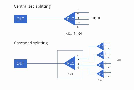
Cascaded splitting means that the optical splitters between the optical line terminal (OLT) and the optical network unit (ONU) are cascaded, and the basic form is “OLT → optical splitter A → optical splitter B → ONU. ”, where the splitting ratio of optical splitter A (the first level) is usually 1:4, and the splitting ratio of optical splitter B ( the second level ) is usually 1:8. In cascaded splittings, the optical splitter A ( the first level) is usually installed near the central office end, and the optical splitter B (the second level ) is usually installed near the user end, such as in a corridor. It is generally used in the following 3 places:
- Splitter A is placed in the central office computer room, and splitter B is placed in the community optical cross-connecting cabinet
- Splitter A is placed in the computer room of the community, and splitter B is placed in the community optical cross-connecting cabinet
- Splitter A is placed in the residential optical cross-connecting cabinet, and splitter B is placed in the corridor
1.1 Pros and cons of different FTTH network splitting methods
| FTTH network splitting level
| Pros | Cons |
| Centralized splitting | OLT utilization (charged as growth) | More distribution fibers |
| Future-proof and easy-to-change technology | Larger network elements in OSP | |
| Monitoring and maintenance | Possible additional infrastructure | |
| Cascading splitting | Lower capital expenditures for customer connections | More fiber splitters |
| Reduced cabinet requirements | Less flexible network | |
| Flexibility of service area allocation ratio | Fewer monitoring and maintenance capabilities |
1.2 Application of different splitting methods in various scenarios
In the construction of FTTH, we should choose the appropriate optical splitting method according to different situations such as community structure, user density, and corridor distribution. The following are the applications of centralized and cascading optical splitting into several common scenarios.
- Villa community
The villa community usually has scattered buildings and long distances; the resident density is low, and a single building may only have one or two residents; the property requirements are high, and aerial cables are not allowed. If the cascading splitting is used, the trunk route is long and a light splitter needs to be placed in each building, which is a serious waste of resources. Therefore, it is recommended to adopt the centralized optical splitting method in the villa community. Set up a centralized point in the community, lead the trunk optical cable to the optical splitter at the centralized point, and then lead it to the fiber distribution box of each building through the distribution optical cable, and then enter the user room through the household optical cable. - Mid-rise building
Mid-rise building is the most widely used scenario for FTTH construction. It is characterized by the regular distribution of buildings, short distances, and high resident density. There are many combinations of line schemes in this type of community, which can be either cascading or centralized, depending on the distance between the community and the access network computer room, and whether there is a computer room in the community. In the FTTH construction, there are requirements for the setting of the OLT equipment at the central office. Generally, only one OLT room is set within a diameter of 5km. Therefore, if the community does not have an OLT room and is far away from the room, it is recommended to use cascading light splitting to save optical cables. Directly put the main optical cable from the OLT room to the corridor, set up an optical splitter in each corridor, and then introduce the user optical cable from the optical splitter to the user room. If the community is very close to the OLT room or if it is possible to build an OLT room, a centralized optical splitter can be used. The optical splitter is installed in the computer room, and the distribution optical cable is pulled from the computer room to the corridor fiber distribution box, and then the user optical cable is introduced into the room. By doing this, it can simplify the complexity of wiring in residential areas and buildings, and is conducive to reducing construction and future maintenance costs and difficulties. - High-rise building
The residents are highly concentrated, and the vertical height of the buildings is relatively high. If the centralized light splitting method is selected, the consumption of the distribution optical cable and the user optical cable is relatively large. Therefore, it is recommended to use cascading optical splitting, pull the main optical cable from the OLT room to the middle floor of the high-rise building, set the number of optical splitters according to the number of households, and then pull the user optical cable from the optical splitter to the user room, which can greatly save the length of the user optical cable and reduce the project investment. At the same time, the reduction in the number of optical cables can free up the upper and lower pipelines in high-rise buildings, reduce the complexity of the optical cables in the building, and help reduce the difficulty of construction and future maintenance. - Rural areas
The characteristics of rural areas are somewhat similar to those of villa communities. The buildings are scattered and irregularly distributed, with long distances and low resident density. It is suitable for centralized light splitting. A light concentration point is set in a relatively concentrated area, and a light splitter is arranged to serve as a radiation point to cover the surrounding area. One of the more prominent problems of this transformation method is that the trunk optical cable needs to be deployed from the OLT equipment room in the urban area to the optical concentration point, the distance will be very long, and the investment will be large. Generally speaking, only 2 cores or 4 cores are needed to open the base station, and there are more hollow cores. We use these hollow cores as the backbone optical cable for FTTH construction, and use the location of the base station as the optical concentration point to cover the surrounding area and make full use of resources.
2. FTTH network splitting ratio
According to the ratio of splitting, the optical splitter can be divided into symmetrical type (eg 1:16 splitting) and asymmetrical type (eg splitting ratio of 10:90). In order to reduce power consumption, make full use of port resources and simplify the calculation of optical path loss, FTTH networks generally use symmetrical optical splitting.
PLC optical splitters often use M×N to indicate that a splitter has M input ends and N output ends. In the FTTx system, M can be 1 or 2, and N can be 2, 4, 8, 16, 32, 64, 128, etc. Optical splitters with different split ratios will play different roles in FTTH networks.
1×32 optical splitter or 1×64 optical splitter is suitable for the centralized splitting (one-level) mode, and 1×4 optical splitter or 1×8 optical splitter is suitable for the cascaded splittings (two-level or more) mode. In addition, if the distance between OLT and ONU is long, a 1×32 optical splitter can be used (transmission distance is usually 20 km), while if the distance between OLT and ONU is short, 1×64 optical splitter can be used.
3. FTTH optical attenuation
At present, FTTH users generally have a splitting ratio of 64, and there are three combinations. The optical splitter without jumper is splitter A (the first level), and the corridor is splitter B (the second level). The splitting ratio of splitter A (the first level) multiplied by splitter B (the second level) equals 64.
Three combinations
- splitter A 1:2, splitter B 1:32, 2×32=64
- splitter A 1:4, splitter B 1:16, 4×16=64
- splitter A 1:8, splitter B 1:8, 8×8=64
Optical attenuation of various optical splitters
| Splitters | Attenuation |
| 1:2 | 3.5db |
| 1:4 | 7db |
| 1:8 | 10db |
| 1:16 | 14db |
| 1:32 | 17db |
3. Summary
FTTH based on PON technology is the trend of future access network development. We should choose an optical splitting method that can save costs and meet future needs according to the actual situation. Bonelinks has many years of experience in R&D, production and manufacturing in the optical communication industry, and has a mature PLC splitter production process. It can provide customers with PLC splitter of various specifications and packaging methods. If you have any need, please contact us.