There are a variety of optical fiber connectors on the market, and their professional terms often confuse newcomers. In today’s article, we will summarize and introduce various types of fiber optic connectors. Only by knowing these interfaces can we correctly purchase fiber jumpers, GBIC fiber optic modules, SFP (mini GBIC) fiber optic modules, fiber optic interface switches, fiber optic transceivers, and couplers (or adapters) in the project.
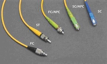
1. In terms of appearance, fiber optic connectors can be divided into FC, SC, LC, Biconic Connector, MU, ST, and so on.
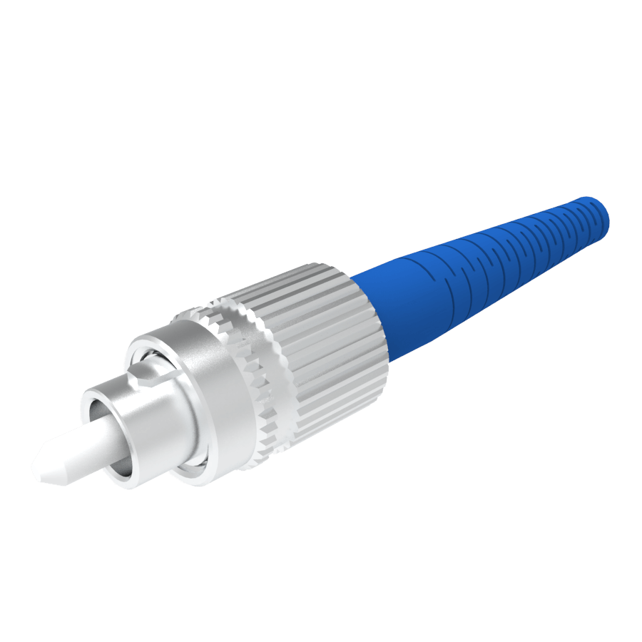
1.1 FC fiber optic connector
The FC connector was first developed by the Japanese NTT company. FC is one of the most common connected devices in single-mode networks. It also uses 2.5mm ferrules, but some of the early FC connectors were designed with ceramic built into stainless steel ferrules. FC has been replaced by SC and LC connectors in most applications today.
FC is the abbreviation of Ferrule Connector, indicating that its external reinforcement is a metal sleeve, and the fastening method is a turnbuckle. The round threaded joint is a metal joint, and the metal joint can be plugged and unplugged more frequently than plastic.
Generally used in telecommunications networks, there is a nut screwed onto the adapter.
Advantages: Reliable and dust-proof.
Disadvantage: slightly longer installation time.
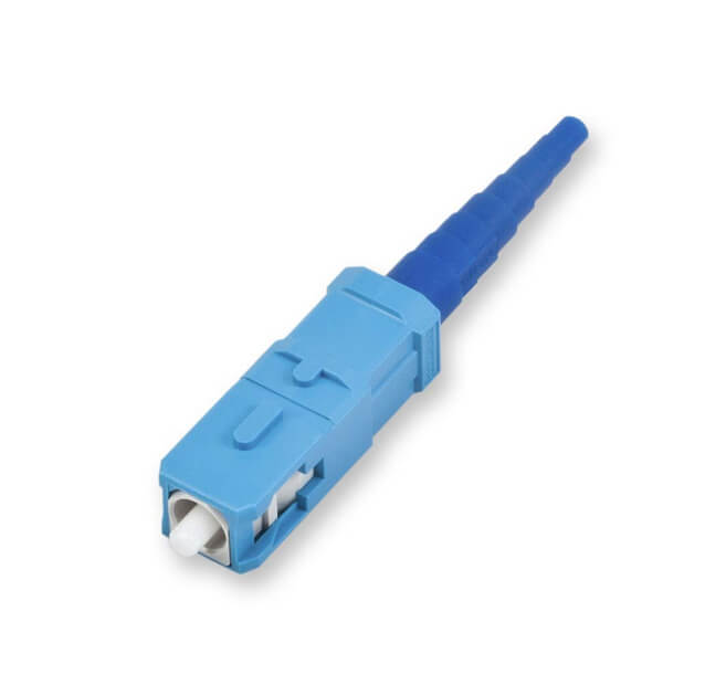
1.2.SC fiber optic connector
SC fiber optic connectors are developed by the Japanese NTT company. SC also has a 2.5mm ferrule. Unlike ST/FC, it is a pluggable device widely used because of its excellent performance. It is a TIA-568-A standardized connector, but initially, it was not widely used due to its high price (twice the price of ST). For 100Base-FX, the connector is mostly SC.
SC is short for “Square Connector”. It is because the shape of SC is always square. The housing is rectangular, and the structure and dimensions of the pins and coupling sleeves are exactly the same as those of the FC. Among them, the end faces of the pins are ground mainly by PC or APC. The fastening method is plug-in latch, no need to rotate.
Advantages: standard square connector, direct plug, easy to use. Made of engineering plastics, resistant to high temperature and not easy to be oxidized.
Disadvantage: The connector is easy to fall out.
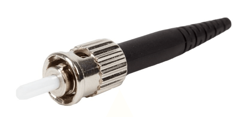
1.3. ST fiber optic connector
ST is perhaps the most common connecting device in multimode networks, such as most in-building or campus networks. For 10Base-F connections, the connectors are usually ST. It is commonly used in fiber optic distribution frames. There are also many photoelectric converters that use such connectors.
It features a bayonet mount and a 2.5mm long cylindrical ceramic (common) or polymer ferrule to hold the entire fiber. The full name of ST is “Stab & Twist”. Its shell is round, and the fixing method is turnbuckle.
Advantages: The connection is tight and not easy to fall off.
Disadvantages: Since the connector needs to be rotated for half a turn after being inserted and fixed by the bayonet, it is easy to break.
1.4. LC fiber optic connector
LC fiber optic connector was first developed by the famous Bell Laboratories (USA), and it is made with a registered jack (RJ) latch mechanism for easy operation. The size of the pins and sleeves used in the LC connector is 1.25mm, which is half the size of ordinary SC and FC. The LC connector is as shown below:
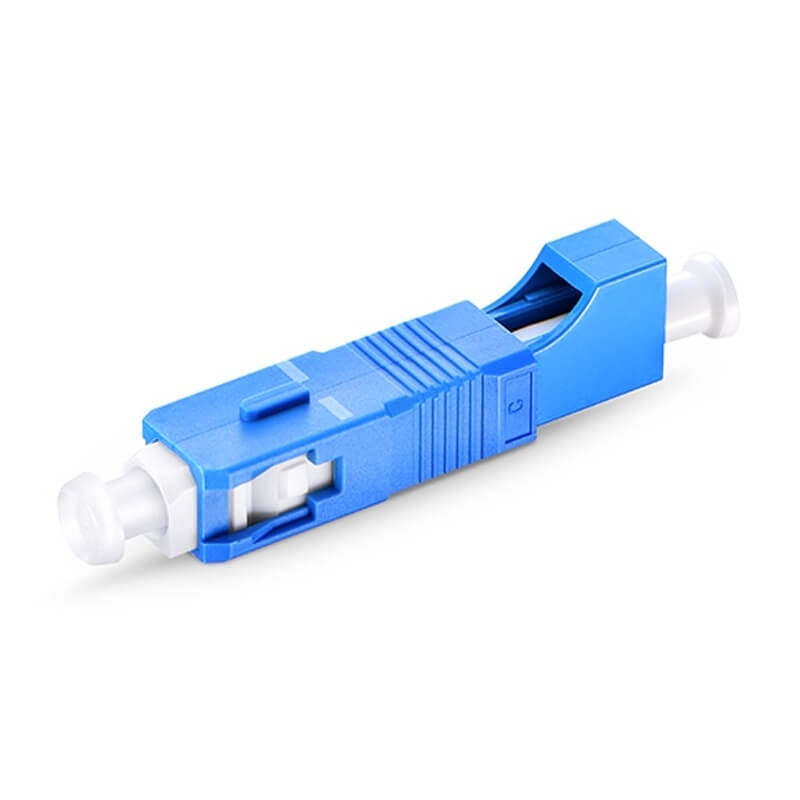
Commonly used LC jumpers are connected to optical fibers and optical modules, so they are generally LC-SC or LC-FC, and most of them are used in pairs, rarely a single LC jumper.
1.5. Biconic connector
Biconic connector: Developed and developed by Bell Labs in the United States, the cylindrical plugs at both ends are conical, and a double-cone plastic sleeve is installed inside. It is named because both ends are tapered, hence the name biconic connector, as shown below:
1.6. DIN47256 fiber optic connector
This is a connector developed in Germany. The pins and coupling sleeves used in this connector have the same structural dimensions as the FC, and the end face treatment adopts PC grinding. Compared with the FC connector, its structure is more complicated, and there is a spring that controls the pressure in the internal metal structure, which can avoid damage to the end face due to excessive insertion pressure. In addition, the mechanical precision of this connector is high, so the insertion loss value is small.
1.7. MT-RJ fiber optic connector
MT-RJ started from the MT connector developed by NTT. It has the same latching mechanism as the RJ-45 LAN electrical connector. It is aligned with the optical fiber through the guide pins installed on both sides of the small sleeve. The optical fiber on the end face of the connector is designed in a double-core (0.75mm interval) arrangement. It is the next-generation high-density optical fiber connector mainly used for data transmission.
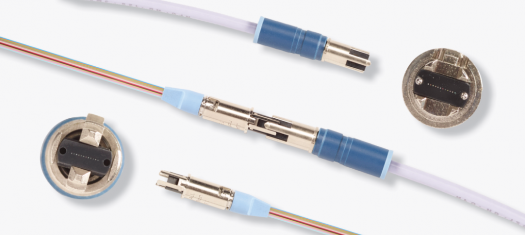
1.8. MU fiber optic connector
MU (Miniature unit Coupling) connector is the world’s smallest single-core optical fiber connector developed by NTT, based on the SC connector that is currently most used. The connector uses a 1.25mm diameter sleeve and a self-retaining mechanism, which has the advantage of enabling high-density mounting. Utilizing MU’s 1.25mm diameter sleeve, NTT has developed the MU connector series. They have receptacle-type connectors (MU-A series) for fiber optic cable connection; backplane connectors (MU-B series) with self-retaining mechanism and simplified receptacles for connecting LD/PD modules to plugs (MU-SR series) and so on. With the rapid development of fiber optic networks in the direction of larger bandwidth and larger capacity and the wide application of DWDM technology, the demand for MU-type connectors will also increase rapidly.
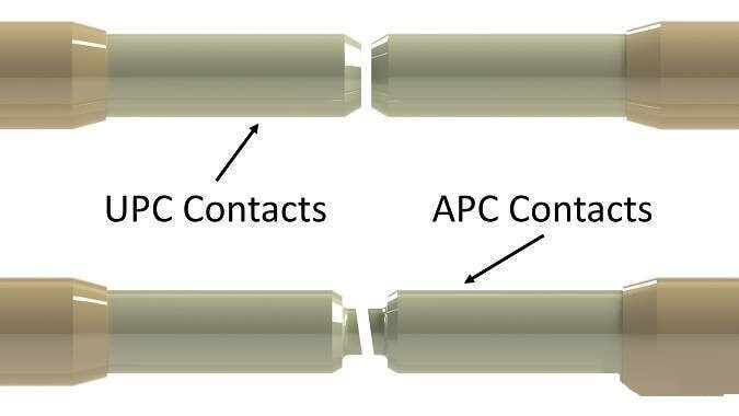
2. According to the shape of the end face of the optical fiber connector and the degree of grinding, the optical fiber connector can be divided into: PC fiber optic connector, SPC fiber optic connector, UPC fiber optic connector and APC fiber optic connector.
Among them, the fiber microsphere end face of PC and UPC is parallel to the end face of the ceramic body, while the fiber microsphere end face of APC and the end face of the ceramic body are at an 8º oblique angle.
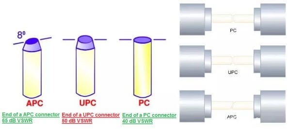
2.1 PC fiber optic connector, SPC fiber optic connector, UPC fiber optic connector
PC refers to physical contact, SPC refers to super physical contact, and UPC refers to ultra physical contact. In terms of performance, UPC is the best, SPC is second, and PC is slightly worse. The performance here is based on the amount of return loss.
Return loss refers to the ratio of back-reflected light to input light in decibels at the fiber connection. The smaller the return loss, the better, so as to reduce the effect of reflected light on the light source and system. The return loss of the PC connector is “-35dB”; the SPC connector is “-40dB”; the UPC connector is “-55dB”. Different connectors cannot be mixed generally, but the fiber end faces of PC, SPC and UPC are all flat, and the difference lies in the quality of grinding. Therefore, the mixed connection of PC, SPC and UPC will not cause permanent physical damage to the connector. The attenuation of UPC is smaller than that of PC. It is generally used for equipment with special needs. Some manufacturers use FC/UPC for internal jumpers of ODF racks, mainly to improve the indicators of ODF equipment itself.
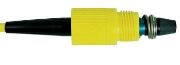
2.2 APC fiber optic connector
APC is completely different. Its end face is ground to an 8-degree angle to reduce reflections, and its industry-standard return loss is -60dB. APC connectors can only be connected to APCs. Since the structure of the APC is completely different from that of the PC, if the two connectors are connected with a flange, the fiber end face of the connector will be damaged. How to connect APC to PC? It is realized through the optical fiber jumper converted from PC to APC. Another thing to note is that APC connectors are usually green (yellow fibers are single-mode fibers), and the inclination of the fiber end face can be seen by the eyes.
3. Fiber optic pigtail meaning and common types
One end with a plug is called fiber optic pigtail. The function of pigtail is mainly used to connect the connectors at both ends of the optical fiber. One end of the pigtail is spliced with the optical fiber connector, and the other end is connected to the optical transceiver or the optical fiber module through a special connector (FC, ST, SC, LC, MTRJ) to form optical data transmission path.
In the annotations representing fiber optic pigtail, we often see “FC/PC”, “SC/PC”, etc. The meanings are as follows:
The part before “/” indicates the connector type of the pigtail, such as FC, SC…
The back of the “/” indicates the cross-section process of the optical fiber connector, that is, the grinding method, such as PC, APC…
Common fiber optic pigtail types:
- FC-SC, that is, the usual round-to-square pigtail. The FC is connected to the ODF box, and the SC is connected to the optical port of the device.
- FC-FC, commonly known as the round-to-round pigtail, is usually used for jumpers between ODF frames.
- SC-SC, commonly known as square-to-square pigtail, is generally used for the connection of optical boards between devices.
- SC-LC, the LC interface is commonly known as a small square pigtail, which is a snap-on type.
- LC-LC, this application is relatively rare, and it is usually used for internal fiber connection between wavelength division equipment.
4. Summary
Generally, when we talk about the type of optical fiber connector, we need to explain its appearance and end face. For example, when we see an FC/PC optical fiber connector, we know that its appearance is FC, and its end face grinding is PC, so we know what kind of base is used to connect it. If you want to learn more, please contact us. All kinds of fiber optic connectors are available at bonelinks.